Load rating of bridges, including substructure

a bridge and load rating technology, applied in the direction of elasticity measurement, structural/machine measurement, instruments, etc., can solve the problem that the process does not address the substructure load rating

Active Publication Date: 2015-10-08
GCI GLOBAL
View PDF0 Cites 22 Cited by
  • Summary
  • Abstract
  • Description
  • Claims
  • Application Information

AI Technical Summary

Problems solved by technology

These procedures do not address substructure load rating other than to point out that the engineer may want to consider it if there is evidence of deterioration.
As a result, the substructure load rating is often based on a qualitative rather that a quantitative approach and may not account for soil behavior and soil-structure interaction.

Method used


Image

  • Load rating of bridges, including substructure
  • Load rating of bridges, including substructure
  • Load rating of bridges, including substructure

Examples


Embodiment Construction

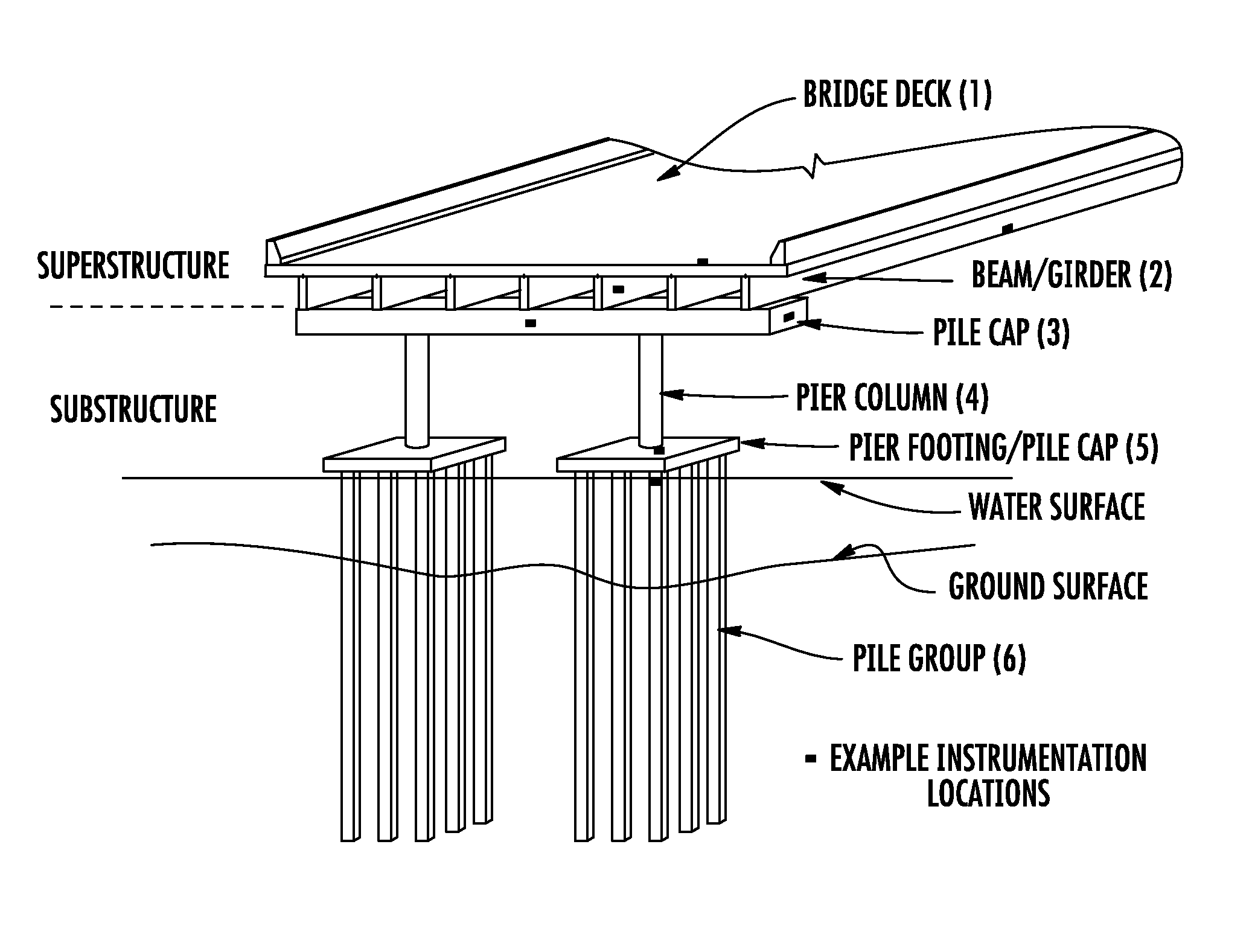
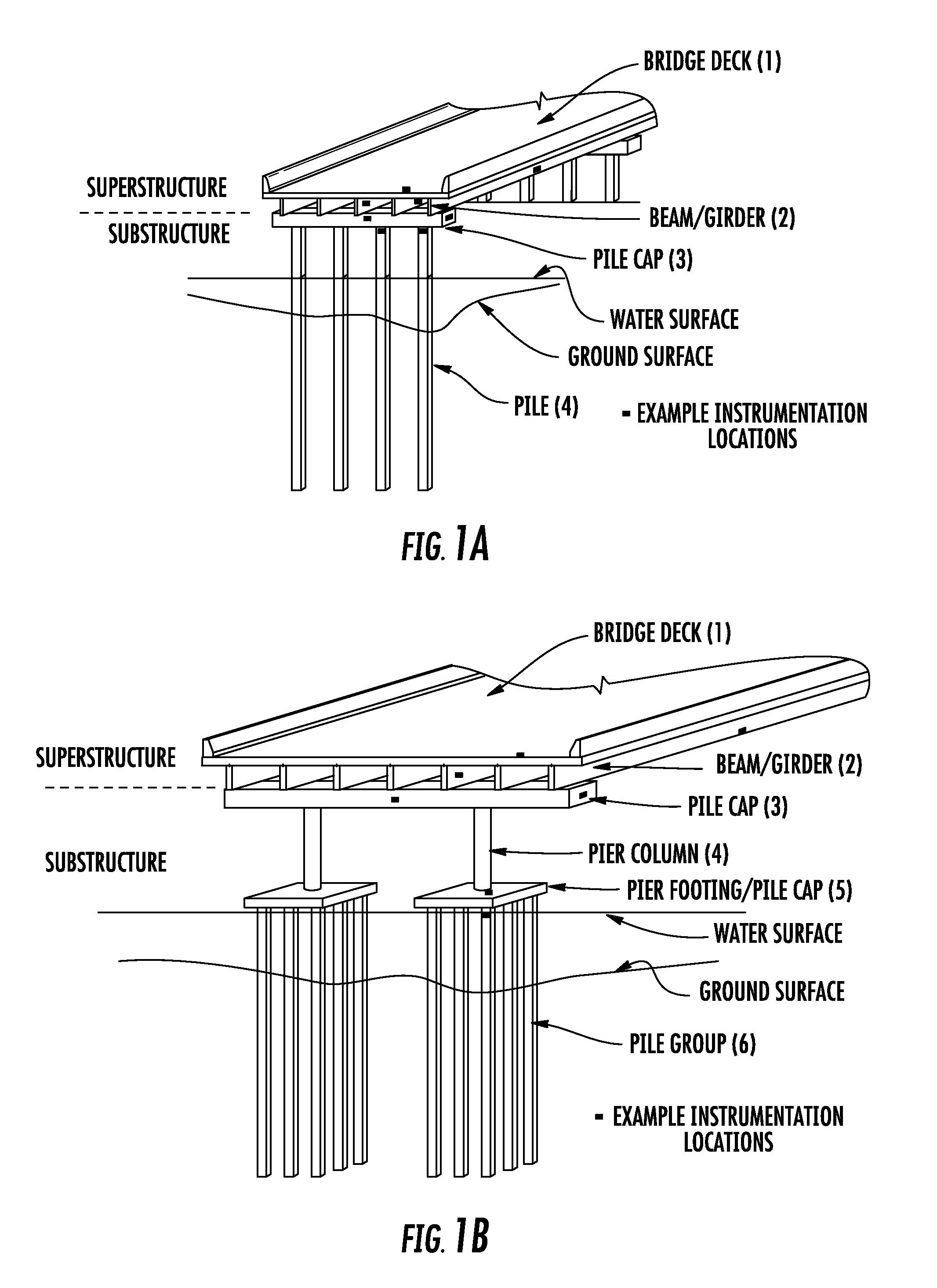
[0013]FIG. 1a illustrates a typical bridge pile bent construction. The bent is supported on piles with known or unknown embedment depth. Drilled shafts may be substituted for piles. As illustrated in FIG. 1a, the superstructure generally includes the bridge deck 1 and beams / girders 2. Some structures might have a deck designed as a flat slab cast directly on the substructure. The typical substructure includes the pile (shaft) cap 3 and the piles (shafts) 4. During service, the loads are transferred from the bridge deck to the soil via the beams / girders, pile (shaft) cap, and then the piles (shafts). Therefore, the soil is ultimately carrying the bridge loads.

[0014]FIG. 1b illustrates a bridge pier construction. As illustrated in FIG. 1b, the superstructure generally includes the bridge deck 1 and beams / girders 2. The substructure includes the pier cap 3, pier columns 4, pile cap / pier footing 5, and piles 6 with known or unknown embedment depth. Drilled shafts may be used instead of ...


PUM

PropertyMeasurementUnit
embedment depthaaaaaaaaaa
specific resistanceaaaaaaaaaa
displacementaaaaaaaaaa

Abstract

For bridges over waterways which are susceptible to scour, the load carrying capacity of the substructure may be reduced by scour. These bridges must be evaluated for reduced load rating and/or posting limits. Here, the substructure load rating is used in connection with calculating the bridge load rating. This is often limited by the substructure load carrying capacity and the tolerable deformation. Thus, bridges impacted by scour need to be judged based on both the superstructure and substructure components. The system/process to assess the substructure load rating uses an analytical method which combines numerical methods and empirical calculations to predict the behavior of a bridge's superstructure and substructure. Limited instrumentation is installed at critical locations on the bridge. The measurements are then used to verify and refine predictions to arrive at a substructure load rating which is usable with the superstructure load rating to define a safe load carrying capacity.

Description

INCORPORATION BY REFERENCE[0001]The following documents are incorporated herein by reference as if fully set forth: U.S. Provisional Patent Application No. 61 / 976,709, filed Apr. 8, 2014.FIELD OF INVENTION[0002]The present disclosure relates generally to a load rating process and, more specifically, to a load rating process for a bridge supported by a deep foundation consisting of either piles or drilled shafts, whether on land or over waterways.BACKGROUND[0003]All roadway bridges whether new or existing must be load rated to determine safe live load carrying capacity. A load rating analysis may be performed as part of the design process for new structures. Load rating for existing structures is reviewed regularly and updated based on the observed condition of the superstructure. Detailed calculation procedures, as published by AASHTO and / or the various state highway departments, are followed. In critical cases which warrant the expense, field verification testing may be performed. ...

Claims


Application Information

Patent Timeline
Patent Type & Authority Applications(United States)
IPC IPC(8): G06F17/50G01M5/00G06F17/10G01N3/00
CPCG06F17/5004G06F17/10G01M5/0008G01N3/00
Inventor SAYED, SAYED MOURADSUNNA, HISHAM NASSIMMOORE, PAMELA RUTH
Owner GCI GLOBAL
Why Eureka
Try Eureka