Active regeneration control method and device for particulate trap

A particulate filter, active regeneration technology, applied in the field of machinery, can solve the problems of DPF pressure difference measurement change, influence the starting time determination, inaccurate carbon load, etc., to ensure accurate control, reduce fuel consumption, carbon load and other problems. accurate and reliable results

Active Publication Date: 2014-01-15
WEICHAI POWER CO LTD
View PDF6 Cites 50 Cited by
  • Summary
  • Abstract
  • Description
  • Claims
  • Application Information

AI Technical Summary

Problems solved by technology

[0004] Since the engine exhaust temperature, especially the DPF temperature during regeneration, will rise sharply, the temperature change will cause the DPF differential pressure measurement to change, resulting in inaccurate carbon load query, affecting the start time of active regeneration control, fuel injection The judgment of the amount and the end time of regeneration leads to poor regeneration effect

Method used


Image

  • Active regeneration control method and device for particulate trap
  • Active regeneration control method and device for particulate trap
  • Active regeneration control method and device for particulate trap

Examples


Embodiment 1

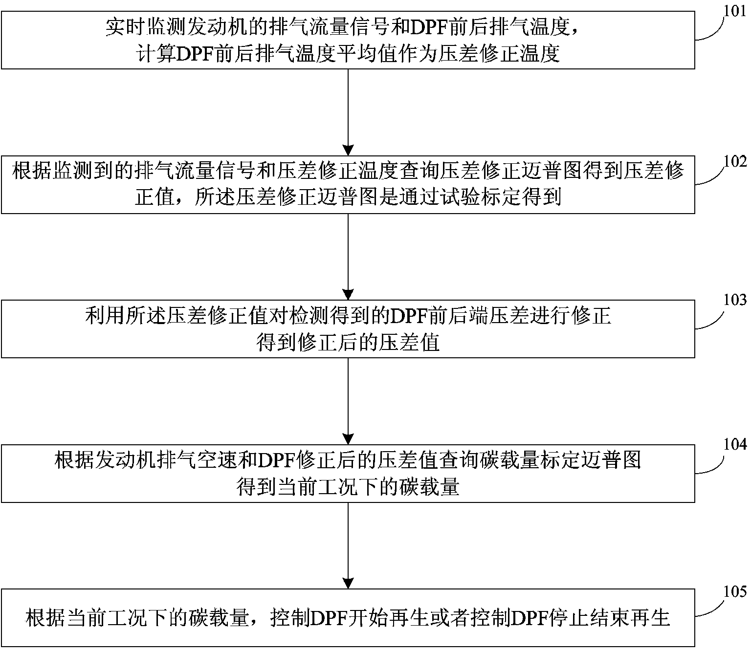
[0044] see figure 1 , which is a method flow chart of an active regeneration control method for a particulate matter trap disclosed in Embodiment 1 of the present invention, specifically including the following steps:

[0045] Step 101: Monitor the exhaust flow signal of the engine and the exhaust gas temperature before and after the DPF in real time, and calculate the average value of the exhaust temperature before and after the DPF as the differential pressure correction temperature;

[0046] Generally, when there are temperature sensors at the front and back of the DPF, the front and rear temperatures can be measured; if there is no temperature sensor at the rear end of some DPFs, preferably, when only the exhaust temperature at the front end of the DPF is monitored, the exhaust temperature at the front end of the DPF is used as the pressure difference Correct the temperature.

[0047] Step 102: According to the monitored exhaust flow signal and differential pressure corre...

Embodiment 2

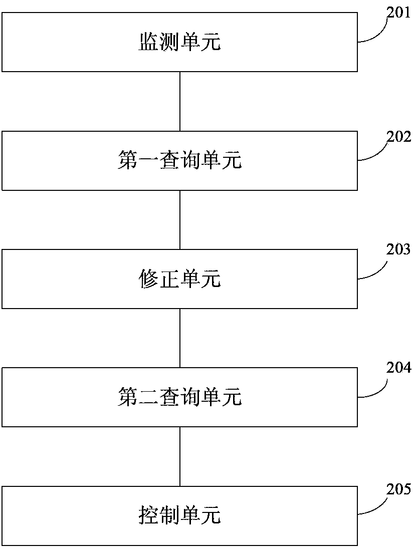
[0060] The present invention also provides an active regeneration control device for particulate matter traps, please refer to figure 2 , which is a schematic structural diagram of an active regeneration control device for a particulate matter trap disclosed in Embodiment 2 of the present invention. The device specifically includes: a monitoring unit 201, a first query unit 202, a correction unit 203, a second query unit 204 and control unit 205 .

[0061] The monitoring unit 201 is used to monitor the exhaust flow signal of the engine and the exhaust gas temperature before and after the DPF, and calculate the average value of the exhaust gas temperature before and after the DPF as the differential pressure correction temperature;

[0062] The first query unit 202 is used to query the differential pressure correction map according to the monitored exhaust gas flow signal and differential pressure correction temperature to obtain a differential pressure correction value, and t...


PUM


Abstract

The invention discloses an active regeneration control method and device for a particulate trap. The method includes the specific steps that monitored pressure difference of a DPF is corrected in real time by monitoring temperature average values before and after exhaust gas of the DPF, accuracy of the pressure difference of the DPF is guaranteed, carbon carrying capacity is obtained through the corrected pressure difference of the DPF and airspeed searching, and therefore accuracy and reliability of the carbon carrying capacity are improved; active regeneration of the particulate trap is controlled according to the carbon carrying capacity, so that the regeneration control is not affected by changes of regeneration temperature and exhaust gas flow of the DPF, and therefore an active regeneration system of the DPF is controlled accurately, active regenerating effect is improved, and fuel oil consumption amount is reduced when active regeneration is performed.

Description

technical field [0001] The invention relates to the field of machinery, in particular to an active regeneration control method and device for a particle trap. Background technique [0002] The main harmful emission from diesel engines is particulate matter, most of which are composed of tiny particles of carbon or carbides. DPF (Diesel Particulate Filter) is a filter device installed on the exhaust system. Its main function is to capture particulate matter before it is discharged into the atmosphere. The captured particulate emissions are burned up during the operation of the vehicle. , can reduce the soot produced by diesel engines to more than 90%. The working principle of the particulate matter filter is: the diesel particulate filter is sprayed with metal platinum and palladium, and the black smoke containing carbon particles discharged from the diesel engine enters the engine exhaust particulate filter through a special pipe, and passes through the densely arranged bel...

Claims


Application Information

Patent Timeline
Patent Type & Authority Applications(China)
IPC IPC(8): F01N9/00F01N3/023
CPCY02T10/40
Inventor 苗垒邓玉龙王军王奉双王胜
Owner WEICHAI POWER CO LTD
Why Eureka
Try Eureka