
Evaporation method and evaporation device

a technology of evaporation method and evaporation device, which is applied in the field of display technology, can solve the problems of reducing product yield, unable to obtain higher ppi, and unable to uniformly distribute the opening regions, so as to achieve the effect of reducing pixel pitch, increasing ppi, and not reducing ppi of produ

Active Publication Date: 2015-10-08
BOE TECH GRP CO LTD +1
View PDF0 Cites 8 Cited by
  • Summary
  • Abstract
  • Description
  • Claims
  • Application Information

AI Technical Summary

Benefits of technology

The present invention provides an evaporation method and an evaporation device for improving the pixel per inch (PPI) and display definition of a product. The technical solution involves using a mask with at least one evaporation sub-pattern to form an evaporation pattern on the substrate, which requires fewer opening regions on the mask compared to prior art methods. This allows for larger shield regions between adjacent opening regions, resulting in a decreased pixel pitch and increased PPI. The technical effect of this invention is to increase the display definition of the product while avoiding the issue of decreased PPI caused by the use of a thick mask with a large number of opening regions.

Problems solved by technology

Even if a FMM is manufactured by using the metal sheet with the minimum thickness, the pixel pitch D′ thereof cannot meet the requirement of being small, and thus, the higher PPI cannot be obtained.
In the current process level of the art, in a case where a thinner metal plate is used for manufacturing the above FMM, the widths of the opening regions cannot remain the same as each other, so that the distribution of the opening regions cannot be uniform, and the product yield is also decreased.
Meanwhile, in order to ensure the product yield and to prevent the FMM from presenting non-uniform distribution of the opening regions, the thickness of a FMM cannot be manufactured to be thin.

Method used


Image

  • Evaporation method and evaporation device
  • Evaporation method and evaporation device
  • Evaporation method and evaporation device

Examples


embodiment 1

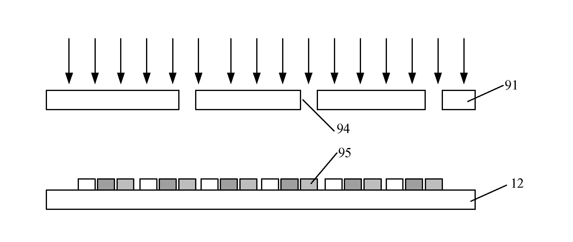
[0057 of the present invention provides an evaporation method, including: successively providing at least one mask above a base substrate and forming at least one evaporation sub-pattern on the base substrate by an evaporation process, so that an evaporation pattern is formed on the base substrate, wherein the evaporation pattern is constituted by the at least one evaporation sub-pattern.

[0058]In Embodiment 1 of the present invention, the evaporation pattern may include a electroluminescent layer or a hole injection layer.

[0059]In Embodiment 1 of the present invention, a FMM may be adopted as the mask.

[0060]In Embodiment 1 of the present invention, some of the evaporation sub-patterns are formed on the base substrate every time the evaporation process is finished, and a predetermined number of evaporation sub-patterns (all of the evaporation sub-patterns constituting the evaporation pattern) are formed on the base substrate after a plurality of the evaporation processes, so that an ...


PUM

PropertyMeasurementUnit
thicknessaaaaaaaaaa
thicknessaaaaaaaaaa
electroluminescentaaaaaaaaaa

Abstract

The present invention discloses an evaporation method and an evaporation device. The evaporation method includes successively providing at least one mask above a base substrate and forming at least one evaporation sub-pattern on the base substrate by an evaporation process so that an evaporation pattern is formed on the base substrate, wherein the evaporation pattern is constituted by the at least one evaporation sub-pattern. As the evaporation pattern finally formed is constituted by the at least one evaporation sub-pattern, only a small number of opening regions are required to be formed on each of the masks used for forming the evaporation sub-patterns compared with the prior art, so that the widths of the shield regions between the adjacent opening regions may be set to be larger.

Description

FIELD OF THE INVENTION[0001]The present invention relates to the field of display technology, and particularly relates to an evaporation method and an evaporation device.BACKGROUND OF THE INVENTION[0002]Fine Metal Masks (simply referred to as FMMs) are commonly used in evaporation processes during the manufacturing processes of Organic Light-Emitting Diodes (simply referred to as OLEDs).[0003]FIG. 1a is a partial plan view of a FMM in the prior art, and FIG. 1b is a section view of FIG. 1a, taken along an A-A direction. As shown in FIG. 1a and FIG. 1b, the FMM includes opening regions 1 and shielding regions 2. The opening regions 1 are used for forming any one of a red electroluminescent layer, a green electroluminescent layer and a blue electroluminescent layer, while the shielding regions 2 is used for shielding the other two electroluminescent layers. For example, in a case where the opening regions 1 are used for forming the red electroluminescent layer (Emission layer, EML for...

Claims


Application Information

Patent Timeline
Patent Type & Authority Applications(United States)
IPC IPC(8): H01L51/00
CPCH01L51/0011H01L51/5088H01L51/5012C23C14/042C23C14/12C23C14/24H10K59/35H10K71/166H10K50/11H10K50/17
Inventor CHEN, JUNSHENGLI, CHENG
Owner BOE TECH GRP CO LTD
Learn More