
Deposition systems having interchangeable gas injectors and related methods

a technology of gas injectors and deposition systems, which is applied in the direction of manufacturing tools, crystal growth processes, polycrystalline material growth, etc., can solve the problem of not being able to clean the deposition chamber in situ in such systems

Inactive Publication Date: 2015-10-15
SOITEC SA
View PDF1 Cites 321 Cited by
  • Summary
  • Abstract
  • Description
  • Claims
  • Application Information

AI Technical Summary

Benefits of technology

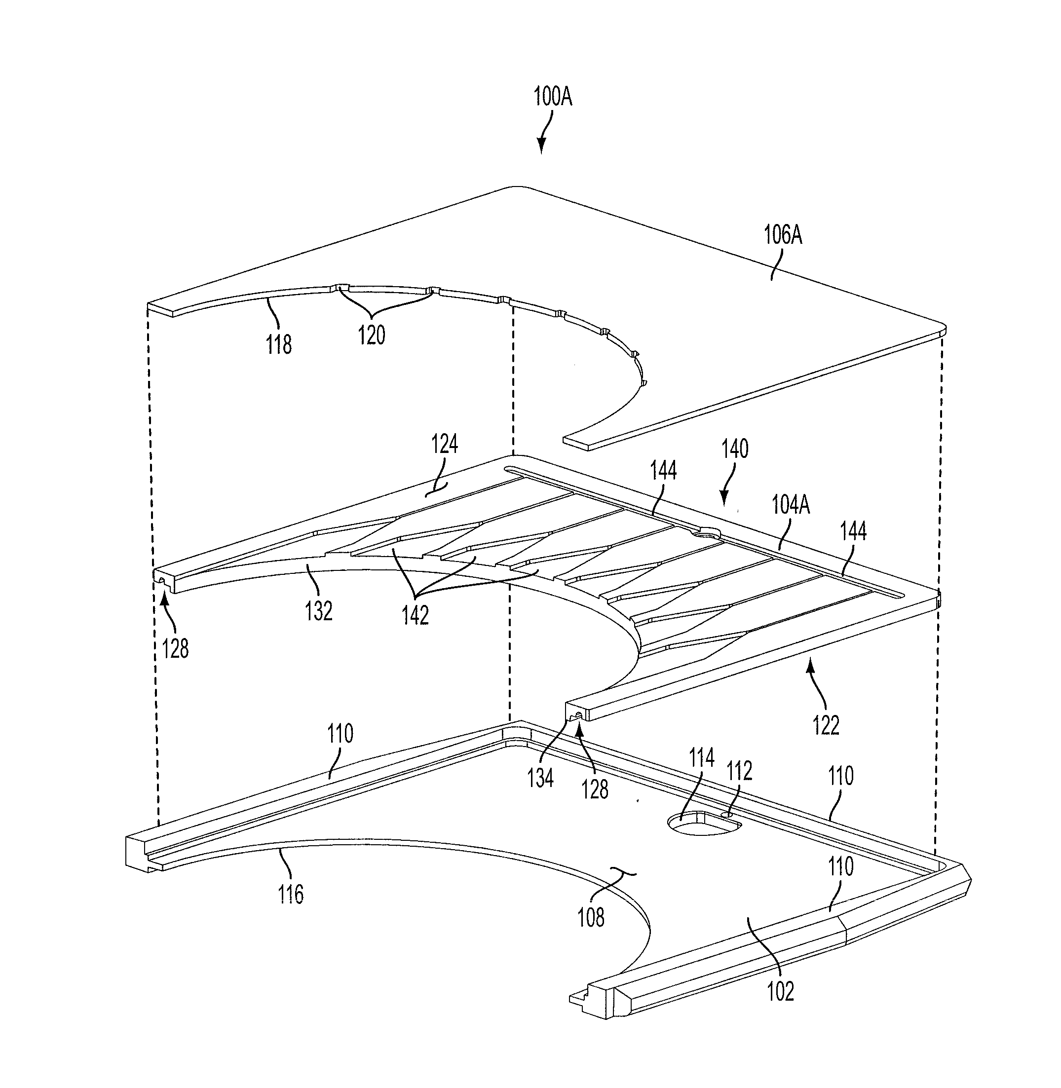
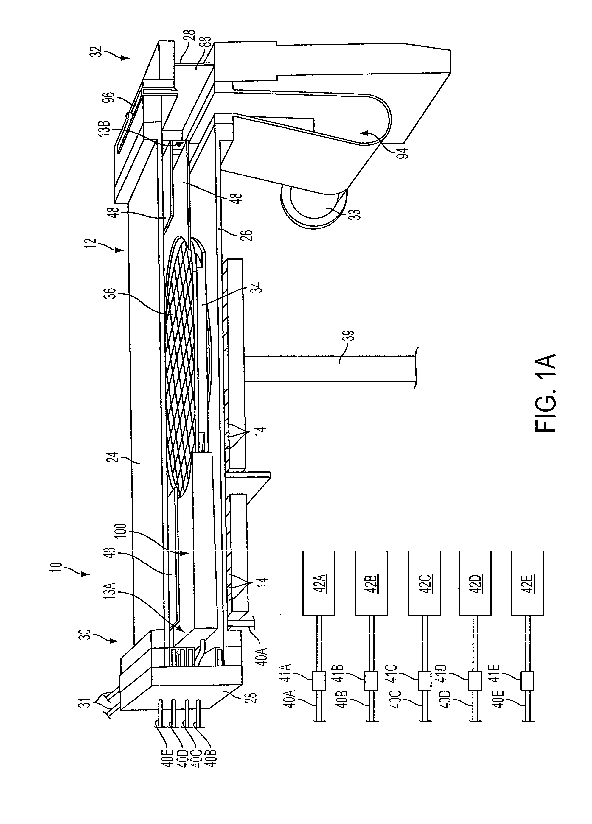
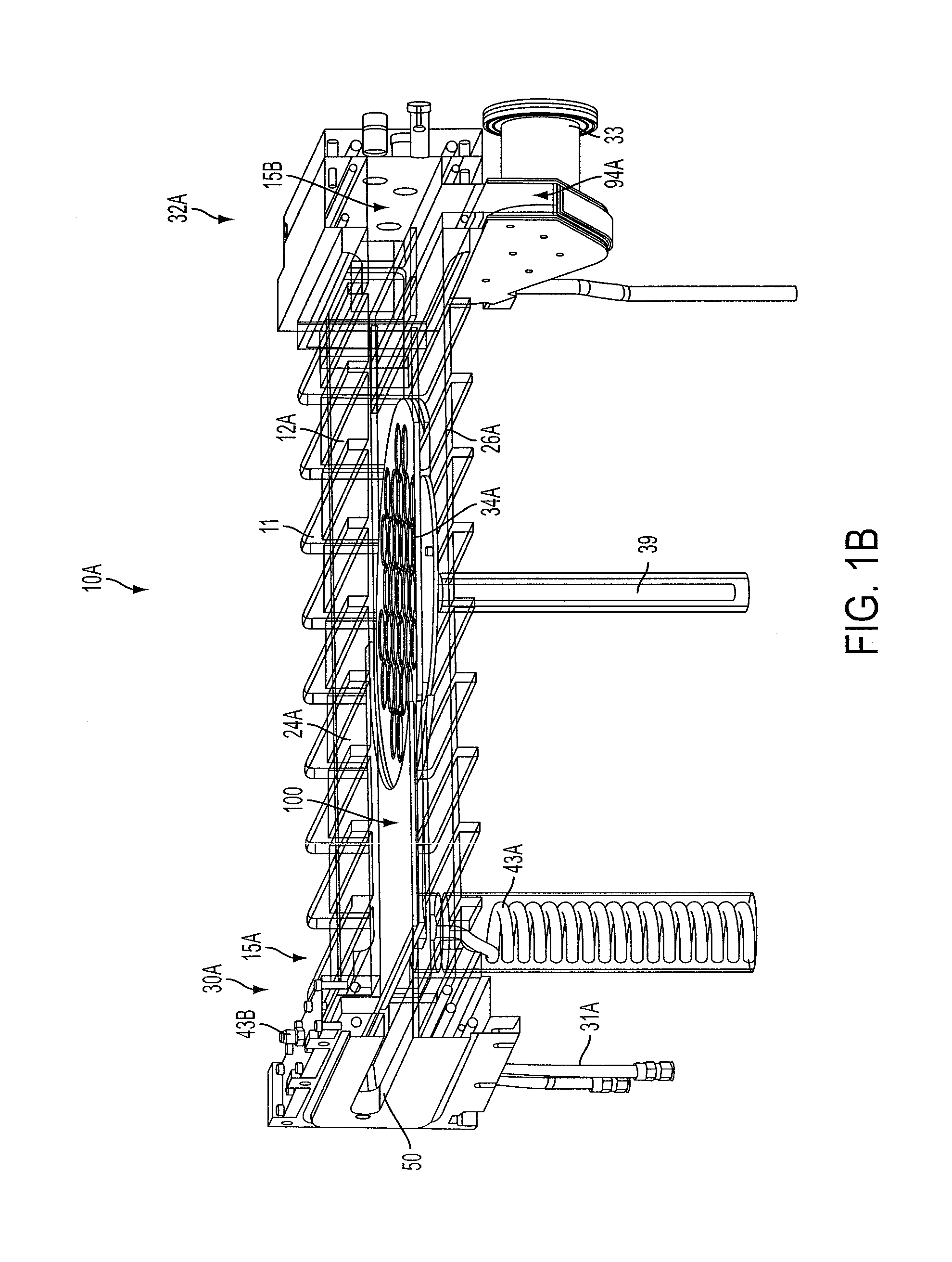
The present patent describes deposition systems and methods for depositing materials onto substrates. The systems include a deposition chamber and a substrate support structure. The substrate support structure has an upper support surface for positioning substrates. The system also includes two gas injectors that can generate a sheet of laminar flowing gas over the substrate during operation of the deposition system. The gas injectors can be interchanged and can generate different sheets of gas with different maximum widths. The methods involve positioning a substrate in the deposition chamber and using the gas injectors to deposit material onto the substrate. The technical effects of the invention include improved deposition precision and flexibility for different substrate sizes.

Problems solved by technology

Furthermore, it may not be possible to clean the deposition chamber in situ in such systems.

Method used


Image

  • Deposition systems having interchangeable gas injectors and related methods
  • Deposition systems having interchangeable gas injectors and related methods
  • Deposition systems having interchangeable gas injectors and related methods

Examples


embodiment 1

[0086]A deposition system, comprising: a deposition chamber; a substrate support structure having an upper support surface configured to support a substrate within the deposition chamber; and at least two gas injectors each configured to be interchangeably seated at a common location within the deposition chamber, each of the at least two gas injectors configured to generate a sheet of generally laminar flowing gas over the substrate support structure during operation of the deposition system, a first gas injector of the at least two gas injectors including two adjoining plates defining one or more gas flow channels therebetween located and configured to generate a sheet of generally laminar flowing gas at an outlet of the first gas injector having a first maximum width transverse to a direction of gas flow in a gas flow plane parallel to the upper support surface of the substrate support structure, a second gas injector of the at least two gas injectors including two adjoining plat...

embodiment 2

[0087]The deposition system of Embodiment 1, wherein the one or more gas flow channels defined between the two adjoining plates of the first gas injector have outlets spanning a first distance transverse to a direction of gas flow in the gas flow plane, and wherein the one or more gas flow channels defined between the two adjoining plates of the second gas injector have outlets spanning a second distance transverse to the direction of gas flow in the gas flow plane, the second distance being smaller than the first distance.

embodiment 3

[0088]The deposition system of Embodiment 1 or Embodiment 2, wherein a difference between the first maximum width and the second maximum width is at least about twenty-five millimeters (25 mm).


PUM

PropertyMeasurementUnit
widthaaaaaaaaaa
temperatureaaaaaaaaaa

Abstract

A deposition system includes two or more gas injectors that may be interchangeably used in a chamber of the deposition system. Each of the gas injectors may be configured to generate a sheet of flowing gas over a substrate support structure. The sheets may have differing widths, such that the gas injectors may be used with substrates having different diameters, which may enable use of the system with different substrates while maintaining efficient use of precursor gas. A method of forming such a deposition system includes forming and configuring such gas injectors to be interchangeably used at a common location within the deposition chamber. A method of using such a deposition system includes using two or more such gas injectors to deposit material on substrates having different sizes.

Description

CROSS-REFERENCE TO RELATED APPLICATIONS[0001]This application is a national phase entry under 35 U.S.C. §371 of International Patent Application PCT / IB2013 / 002604, filed Nov. 20, 2013, designating the United States of America and published in English as International Patent Publication WO 2014 / 083400 A1 on Jun. 5, 2014, which claims the benefit under Article 8 of the Patent Cooperation Treaty and under 35 U.S.C. §119(e) to U.S. Provisional Patent Application Ser. No. 61 / 730,393, filed Nov. 27, 2012, the disclosure of each of which is hereby incorporated herein in its entirety by this reference.TECHNICAL FIELD[0002]The present disclosure relates to deposition systems that have interchangeable gas injectors, as well as to methods of making and using such deposition systems.BACKGROUND[0003]Semiconductor structures are structures that are used or formed in the fabrication of semiconductor devices. Semiconductor devices include, for example, electronic signal processors, electronic memor...

Claims


Application Information

Patent Timeline
Patent Type & Authority Applications(United States)
IPC IPC(8): C23C16/455H01L21/02B23P19/04
CPCC23C16/45563H01L21/0262C23C16/45504B23P19/04C30B25/14C30B29/403C23C16/45591C30B35/00
Inventor CANIZARES, CLAUDIO
Owner SOITEC SA
Learn More