
Heat exchanger and method for heating a fracturing fluid

Inactive Publication Date: 2015-10-15
MARALTO ENVIRONMENTAL TECH
View PDF48 Cites 6 Cited by
  • Summary
  • Abstract
  • Description
  • Claims
  • Application Information

AI Technical Summary

Benefits of technology

[0010]In one embodiment of the heat exchanger first described above, each heat pipe comprises a sealed tube containing a heat transfer substance that migrates from the hot end to the cold end when the heat tran

Problems solved by technology

The venting of hot flue gases into the atmosphere is potentially undesirable in that it wastes the thermal energy of the flue gas, and can heat the environment surrounding the combustion device.
The use of the tube to transfer the hot flue gas or the cooling medium presents potential design problems.
However, such design selections also tend to increase the tube's susceptibility to internal fouling and internal resistance to fluid flow.
Although heat exchangers in the prior art fulfill the objective of extracting heat from the hot flue gas, their effectiveness may be limited by practical design considerations.

Method used


Image

  • Heat exchanger and method for heating a fracturing fluid
  • Heat exchanger and method for heating a fracturing fluid

Examples


Embodiment Construction

[0032]The present invention relates to a heat exchanger and method for heating a fluid with flue gas. To the extent that the following description is of a specific embodiment or a particular use of the invention, it is intended to be illustrative only, and not limiting of the claimed invention. As will be apparent to those skilled in the art, various modifications, adaptations and variations of the foregoing specific disclosure can be made without departing from the scope of the invention claimed herein.

[0033]When describing the present invention, all terms not defined herein have their common art-recognized meanings. To facilitate understanding of the invention, the following terms are defined.

[0034]As used herein, the term “fluid” refers to any flowable substance that continually deforms under an applied shear stress, and includes substances in the liquid and gas phase. Fluid may include, without limitation, fracturing fluid and flue gas.

[0035]As used herein, the term “hot fluid” ...


PUM


Abstract

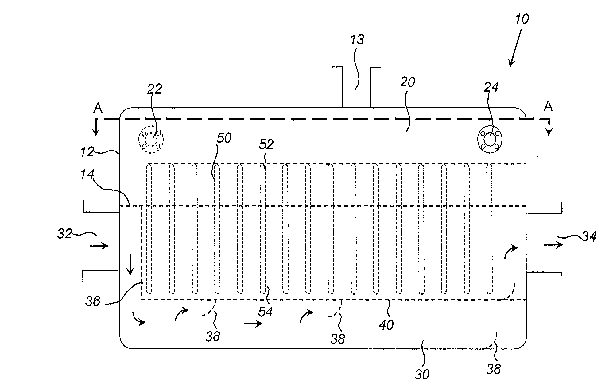
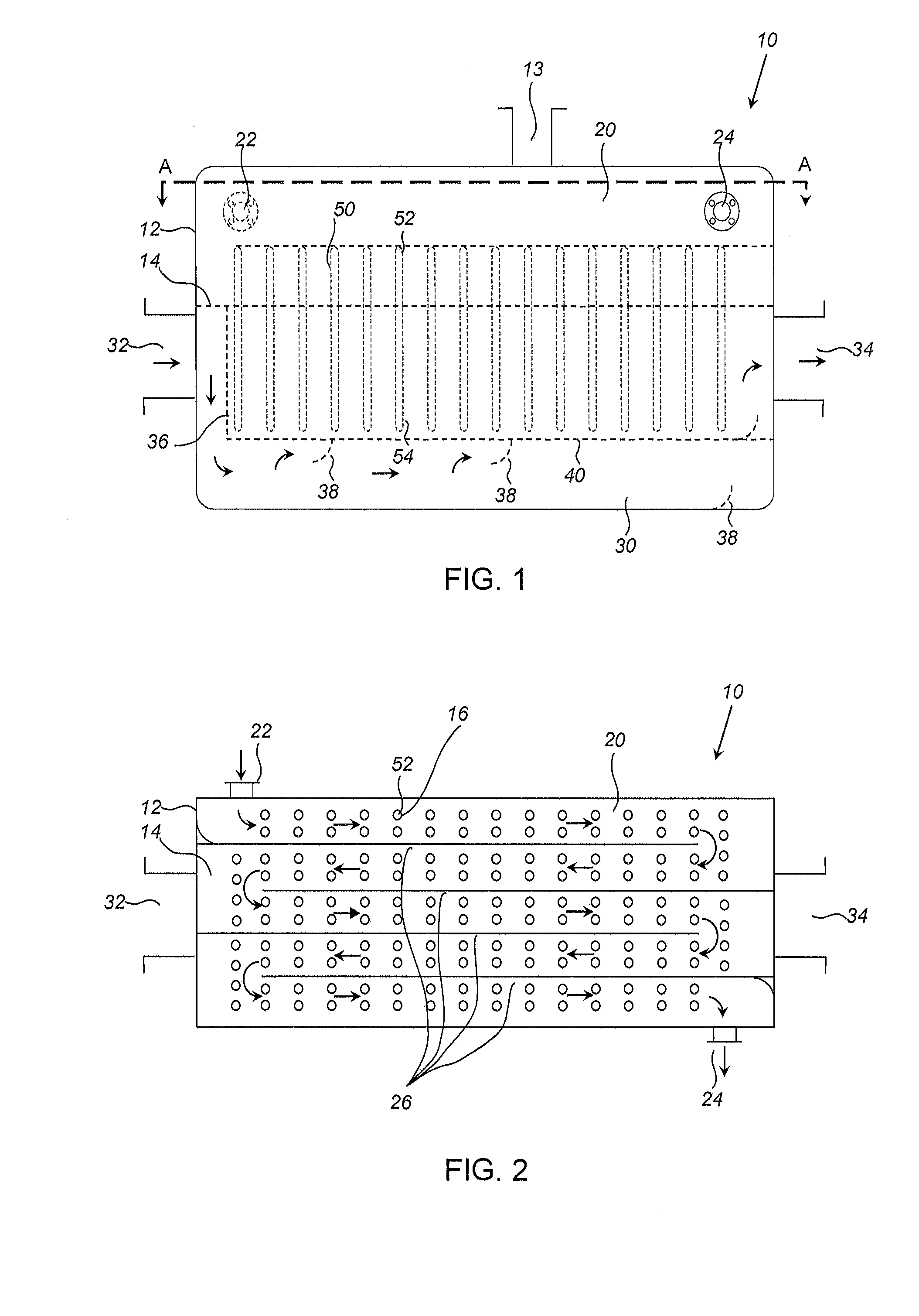
A heat exchanger comprises a shell internally divided into a hot fluid vessel and a cold fluid vessel by a pipe retaining plate having a plurality of apertures sealingly retaining a corresponding number of heat pipes, each of which has a hot end in the hot fluid vessel and a cold end in the cold fluid vessel. The hot fluid vessel is internally configured to direct a hot fluid through a porous dispersion plate that distributes the hot fluid amongst the hot ends of the heat pipes. The cold fluid vessel has an internal baffle that defines a serpentine channel that guides a cold fluid through the cold fluid vessel. Fracturing fluid may be heated by streaming flue gas exhausted from an incinerator through the hot fluid vessel while simultaneously streaming the fracturing fluid through the cold fluid vessel.

Description

FIELD OF THE INVENTION[0001]The present invention relates to a heat exchanger and method for using the heat exchanger to heat a fracturing fluid using flue gas.BACKGROUND OF THE INVENTION[0002]Combustion devices such as incinerators used for waste management, power generation and industrial processes typically produce an exhaust stream of hot flue gases. The venting of hot flue gases into the atmosphere is potentially undesirable in that it wastes the thermal energy of the flue gas, and can heat the environment surrounding the combustion device. If instead the waste heat can be extracted from the flue gas before venting, then the energy efficiency of the overall system can be increased by recycling the extracted heat for heating the combustion device or other uses of the heat, while mitigating the environmental impact of the hot flue gas.[0003]In the prior art, many heat exchangers for extracting waste heat from flue gases, such as “shell and tube” heat exchangers, operate on the pr...

Claims


Application Information

Patent Timeline
IPC IPC(8): F28D15/02
CPCF28D15/02F23J15/06F28F9/0131F28D15/0275E21B43/2607Y02E20/30
Inventor ROMEO, MARLIN
Owner MARALTO ENVIRONMENTAL TECH
Learn More