Aberration correction optical unit and laser microscope

a laser microscope and optical unit technology, applied in the field of optical system abreast correction technique, can solve the problems of generating aberration due to the objective lens, reducing resolution, and reducing the accuracy of the objective lens, and achieve automatic optimizing the position and improving the resolution

Active Publication Date: 2015-10-15
CITIZEN WATCH CO LTD
View PDF4 Cites 13 Cited by
  • Summary
  • Abstract
  • Description
  • Claims
  • Application Information

AI Technical Summary

Benefits of technology

[0033]According to the invention, in observing a deep portion of a biospecimen or observing a specimen through a cover glass, an aberration correction optical unit and a laser microscope incorporated with the aberration correction optical unit can correct an aberration generated by deviation of the thickness of a cover glass from an estimated value and observing the specimen with enhanced resolution. In particular, the aberration correction optical unit and the laser microscope can correct an aberration appropriately by optimally controlling a polarization characteristic of the aberration correction optical unit in accordance with polarization characteristics of laser light illuminating a specimen and fluorescence generated from the specimen. Further, the aberration correction optical unit and the laser microscope are operable to electrically correct an aberration without the need of touching the objective lens by hand. This is advantageous in automatically optimizing the position of the objective lens and in adjusting the position of the objective lens in synchronization with an observation depth in the Z stacking process, without the cumbersomeness such as adjusting a correction ring.
[0034]Further, the aberration correction optical unit and the laser microscope are capable of correcting an aberration having a magnitude up to twice that of an existing aberration by controlling the aberration correction optical unit in accordance with an observation mode of a microscope such as a confocal laser microscope or a multi-photon microscope.

Problems solved by technology

Further, generally, the objective lens is designed so that an imaging performance is best at a position immediately below the cover glass having a predetermined thickness and therefore, an aberration due to the objective lens is generated when an optical path length to an observation plane is changed.
In observing the inside of a biospecimen, it is necessary to acquire an image at an observation position equivalent to a depth where a broth or biological tissues are transmitted, and an aberration is generated in proportion to a distance from a position immediately below the cover glass to the observation position, resulting in a decrease in resolution.
However, the refractive index of the biospecimen is not equal to the refractive index of water and therefore, an aberration is also generated due to a difference between the refractive index of the biospecimen and the refractive index of water.
Therefore, a decrease in resolution is still problematic.

Method used


Image

  • Aberration correction optical unit and laser microscope
  • Aberration correction optical unit and laser microscope
  • Aberration correction optical unit and laser microscope

Examples


Embodiment Construction

[0049]In the following, an aberration correction optical unit and a laser microscope incorporated with the aberration correction optical unit according to preferred embodiments of the invention are described in detail referring to the accompanying drawings.

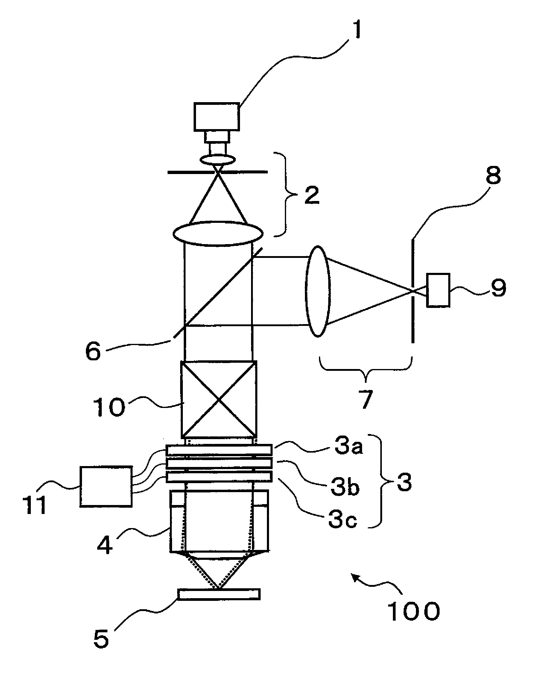
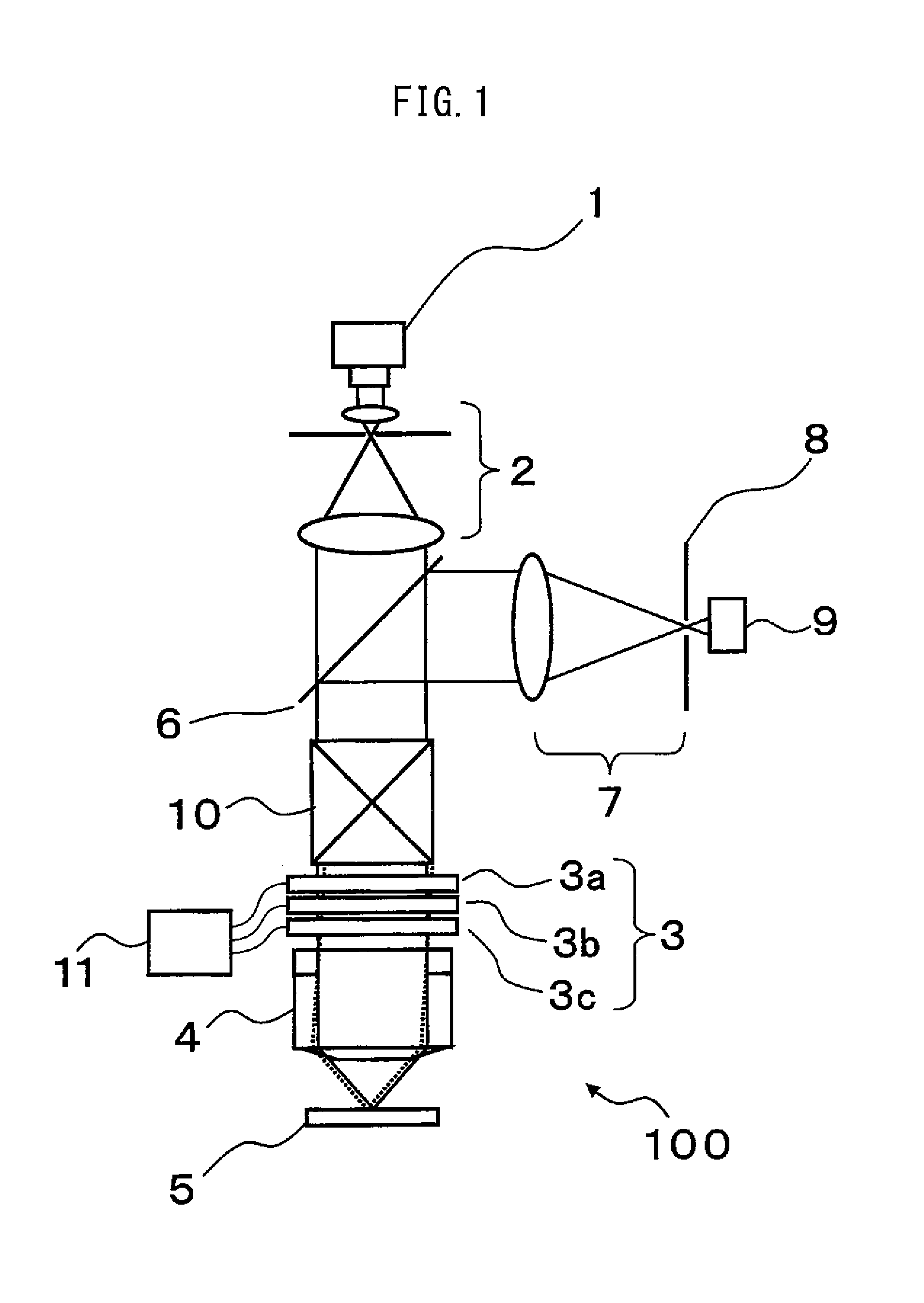
[0050]FIG. 1 is a schematic configuration diagram of a laser microscope 100 according to one embodiment of the invention. A light flux emitted from a laser light source 1 as a coherent light source is adjusted by a collimating optical system 2 into a parallel light. The parallel light is transmitted through an aberration correction optical unit 3 and thereafter, focused on a specimen 5 through an objective lens 4. A light flux including specimen information such as a light flux reflected or scattered on the specimen 5 or fluorescence generated on the specimen returns through an optical path, reflected by a beam splitter 6, and focused again on a confocal pinhole 8 by a confocal optical system 7 as a second optical system. The conf...


PUM

PropertyMeasurementUnit
angleaaaaaaaaaa
refractive indexaaaaaaaaaa

Abstract

An aberration correction optical unit (3) disposed in an optical system includes: a first phase modulation element (3a) and a second phase modulation element (3c) each having a polarization characteristic; and a variable waveplate (3b) disposed between the first and second phase modulation elements so that an optical axis of the variable waveplate has a predetermined angle with respect to optical axes of the two phase modulation elements, in order to correct an aberration generated by the optical system.

Description

TECHNICAL FIELD[0001]The present invention relates to an aberration correction technique for an optical system and to a technique for controlling an aberration, which is generated depending on a specimen or an observation condition, in accordance with an observation mode or specifications of a microscope, specifically, a laser microscope.BACKGROUND ART[0002]A laser microscope focuses laser light on a specimen through an objective lens and scans the specimen with the laser light in two directions (X-direction and Y-direction) orthogonal to each other along a plane perpendicular to an optical axis to acquire a planar image of the specimen. On the other hand, a plurality of tomographic images (Z-stack images) along the Z-direction are obtained by changing a distance along the optical axis direction (Z-direction) between the objective lens and the specimen, whereby the laser microscope forms a three-dimensional image of the specimen.[0003]In a confocal laser microscope which is the main...

Claims


Application Information

Patent Timeline
Patent Type & Authority Applications(United States)
IPC IPC(8): G02B21/00G02F1/01G02F1/1347G02B27/00
CPCG02B21/0072G02B27/0068G02B21/0068G02F1/1347G02F1/0136G02B27/0031G02F2203/18G02B21/00G02B21/0024G02B21/0032G02B21/0092G02B21/06G02F1/13
Inventor MATSUMOTO, KENJI
Owner CITIZEN WATCH CO LTD
Why Eureka
Try Eureka