Electric compressor

a compressor and electric technology, applied in the direction of motor/generator/converter stopper, machine/engine, process and machine control, etc., can solve the problems of carrier noise, large switching loss, damage to components of inverter circuit, etc., to reduce the number of switching operations in the temperature rise period, suppress the rise in temperature of inverter circuit, the effect of reducing the number of switching operations

Active Publication Date: 2015-10-15
DENSO CORP
View PDF2 Cites 17 Cited by
  • Summary
  • Abstract
  • Description
  • Claims
  • Application Information

AI Technical Summary

Benefits of technology

[0012]In the temperature rise period, the carrier frequency is changed according to the value detected by the physical quantity detector so that the carrier frequency of the reference carrier decreases with increase of the temperature of the switching elements at the startup of the motor. Accordingly, the number of the switching operations in the temperature rise period can be reduced and the rise in temperature of the inverter circuit can be suppressed in a case where the temperature of the switching elements at the startup of the motor is relatively high. In this manner, the inverter circuit can be prevented from reaching an excessively high temperature.
[0013]In the period after the stopping of the rise in temperature, the carrier frequency is changed according to the number of revolutions of the compression mechanism or the physical quantity associated with the number of revolutions of the compression mechanism, so that the carrier frequency decreases with increase of the number of revolutions of the compression mechanism,

Problems solved by technology

Accordingly, the inverter device according to the conventional technology has a problem in that switching loss is relatively large immediately after the motor startup and the like and the temperature of an inverter circuit overshoots to be likely to reach a relatively high temperature.
When the temperature of the inverter circuit is excessively high, components constituting the inverter circuit may be damaged in some cases.
Another problem is that carrier noise (noise that i

Method used


Image

  • Electric compressor
  • Electric compressor
  • Electric compressor

Examples


Embodiment Construction

[0025]Hereinafter, multiple embodiments for implementing the present invention will be described referring to drawings. In the respective embodiments, a part that corresponds to a matter described in a preceding embodiment may be assigned the same reference numeral, and redundant explanation for the part may be omitted. When only a part of a configuration is described in an embodiment, another preceding embodiment may be applied to the other parts of the configuration. The parts may be combined even if it is not explicitly described that the parts can be combined. The embodiments may be partially combined even if it is not explicitly described that the embodiments can be combined, provided there is no harm in the combination.

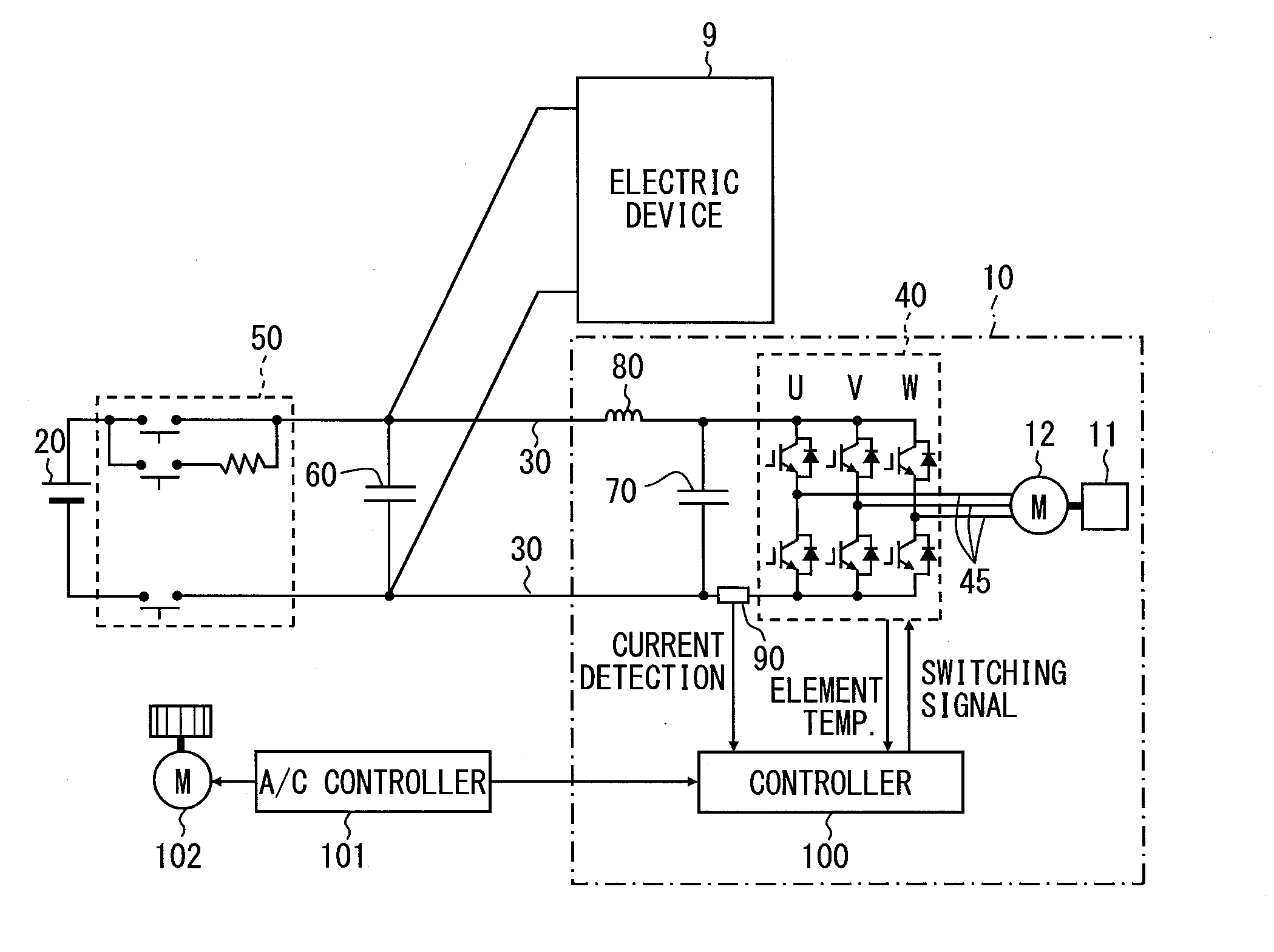
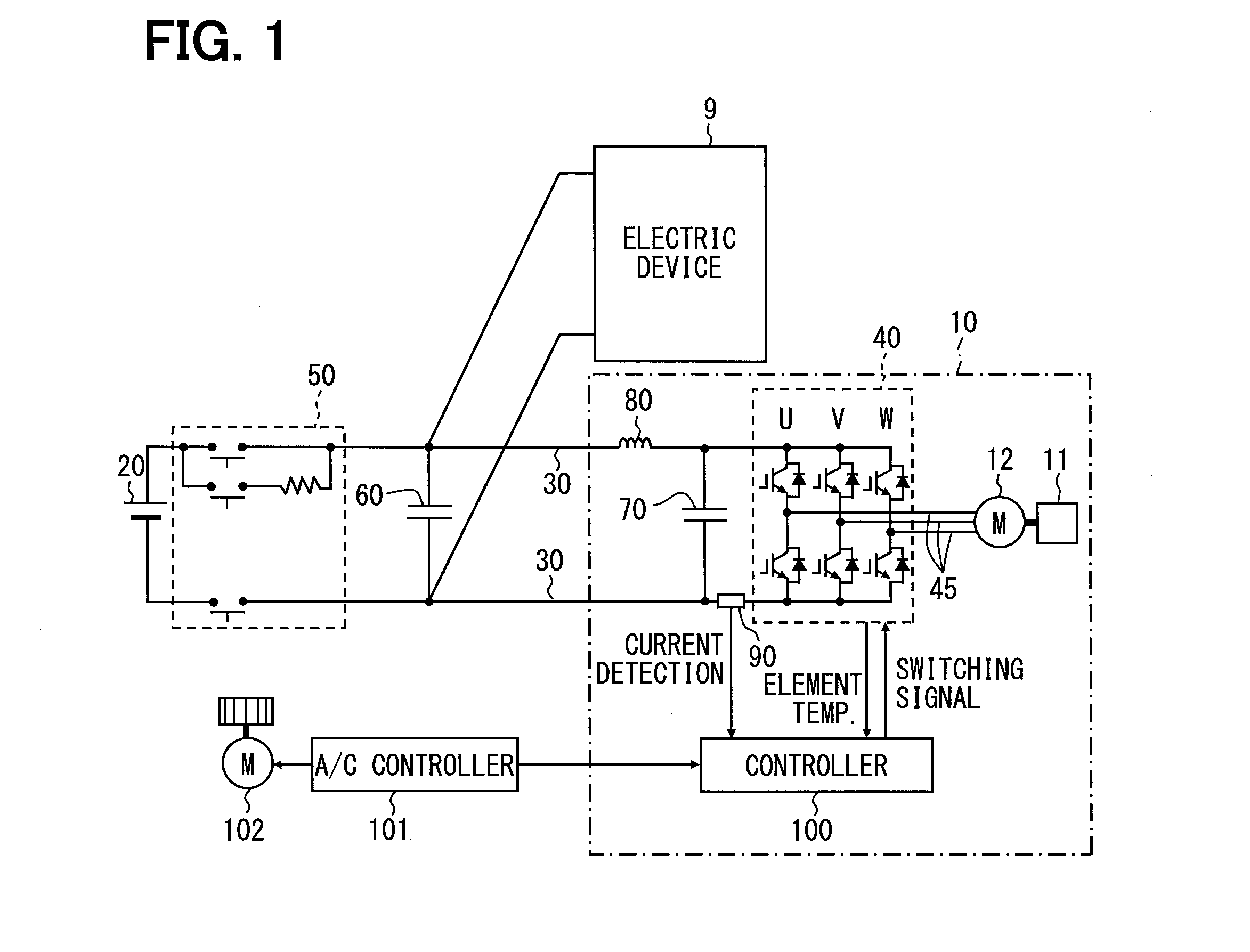
[0026]An embodiment to which the present disclosure is applied will be described with reference to FIGS. 1 to 10.

[0027]As illustrated in FIG. 1, a motor driving device of an electric compressor 10 of the embodiment drives a synchronous motor 12. The electric com...


PUM


Abstract

A controller for an electric compressor sets a temperature rise region A, a temperature drop region B, and a steady region C from change in temperature of switching elements, and sets a carrier frequency for each of the set regions. In the region A, the carrier frequency is changed according to the element temperature so that the carrier frequency decreases with increase of the element temperature at startup of a motor. In the region B and the region C, the carrier frequency is changed according to the number of revolutions of a compression mechanism, so that the carrier frequency decreases with increase of the number of revolutions of the compression mechanism, regardless of the element temperature.

Description

CROSS REFERENCE TO RELATED APPLICATION[0001]This application is based on and incorporates herein by reference Japanese Patent Application No. 2012-158973 filed on Jul. 17, 2012.TECHNICAL FIELD[0002]The present disclosure relates to an electric compressor in which an inverter circuit that drives an electric motor is cooled by an intake refrigerant taken in by a compression mechanism.BACKGROUND ART[0003]Conventionally, an inverter device that detects the temperature of a switching element and changes a carrier frequency according to the detected temperature is known. The inverter device is known to lower the carrier frequency in stages from an initially set frequency when the detected temperature is at least an upper limit reference temperature, and to return the carrier frequency to the initially set frequency when the detected temperature is equal to or lower than a lower limit reference temperature (refer to Patent Document 1 below).PRIOR ART DOCUMENTPatent Document[0004]Patent Doc...

Claims


Application Information

Patent Timeline
IPC IPC(8): H02P29/02H02P6/00
CPCH02P6/002H02P29/02F04B49/06H02M7/53871F04C28/06F04C28/28F04C18/0215F04C2240/403F04C2240/81F04C29/047F04C2240/808F04B35/04F04B49/065F04B49/103F04B2203/0201F04B2203/0202F04B2203/0205H02M1/36H02M7/5387H02P27/085H02P6/28H02P29/68H02P23/24H02M1/327H02H7/08G06F1/06H02H6/00H02P23/0027
Inventor SAKAI, KOJI
Owner DENSO CORP
Why Eureka
Try Eureka