
Arthroscopic instrument assembly, and method of localizing musculoskeletal structures during arthroscopic surgery

a technology of arthroscopic instruments and musculoskeletal tissue, which is applied in the field of arthroscopic instrument assembly and the field of localizing musculoskeletal tissue structures, can solve the problems of difficult graft attachment accuracy and achieve the effect of facilitating the localization of native attachment sites

Inactive Publication Date: 2015-10-22
ACADEMISCH MEDISCH CENT BIJ DE UNIV VAN
View PDF0 Cites 15 Cited by
  • Summary
  • Abstract
  • Description
  • Claims
  • Application Information

AI Technical Summary

Benefits of technology

The present invention provides an arthroscopic instrument assembly that makes it easy to locate the attachment sites of the ACL (anterior cruciate ligament) in a knee joint during arthroscopic surgery. Additionally, the invention is about a method that can help identify both ligament and bone tissues in an operative field and enhance the contrast between them using light having a specific wavelength. This makes it easier to locate specific ligament structures within the joint.

Problems solved by technology

However, despite the fact that the anatomical position of the ACL has been geometrically described and charted relative to arthroscopically visible landmarks of the tibia and the femur in various studies, accurate attachment of the graft remains difficult.
This may be at least partially due to the limited, two-dimensional view provided by an arthroscope, which appears to render the aforementioned descriptions and landmarks insufficient for correctly positioning the graft during arthroscopic surgery.

Method used


Image

  • Arthroscopic instrument assembly, and method of localizing musculoskeletal structures during arthroscopic surgery
  • Arthroscopic instrument assembly, and method of localizing musculoskeletal structures during arthroscopic surgery
  • Arthroscopic instrument assembly, and method of localizing musculoskeletal structures during arthroscopic surgery

Examples


Embodiment Construction

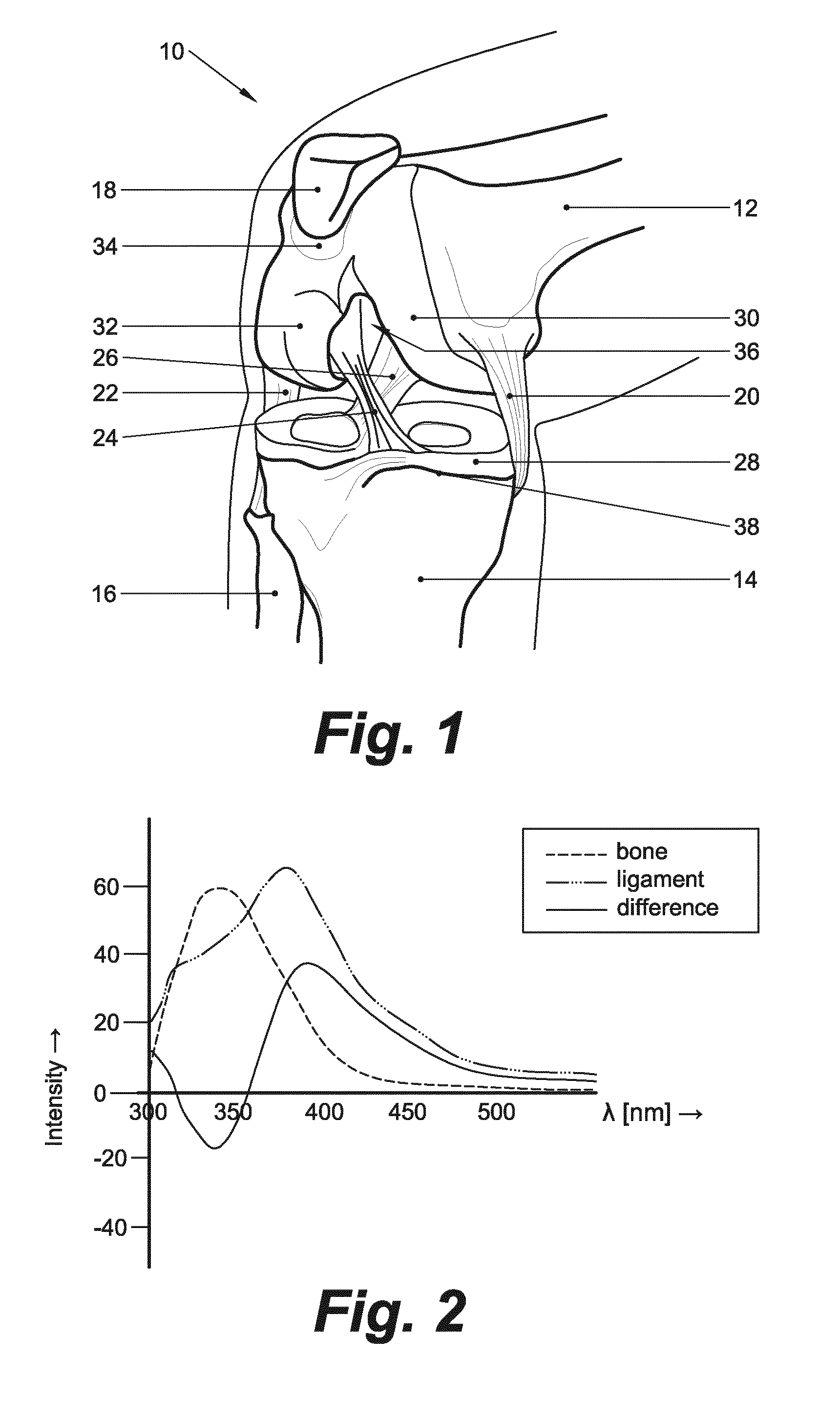
[0014]FIG. 1 schematically illustrates a human knee 10 in an approximately 90° flexed condition. The knee 10 is made up of four major bones: the femur (thigh bone) 12, the tibia (shin bone) 14, the fibula (outer shin bone) 16, and the patella (knee cap) 18. The fibula 16 is a relatively thin bone that lies at the outside of the tibia 14 and travels right down to the ankle joint. The other three bones define two articulations, one between the femur 12 and the tibia 14, and one between the femur 12 and the patella 18. To this end, the lower end of the femur 12 defines two condyles (i.e. rounded prominences), the medial (inner) femoral condyle 30 and the lateral (outer) femoral condyle 32, which articulate with the tibial plateau, i.e. the generally flat upper portion of the tibia 14. Anteriorly, the femoral condyles 30, 32 are slightly prominent and separated from one another by a smooth, shallow articular depression called the patellar surface 34, which articulates with the patella 1...


PUM


Abstract

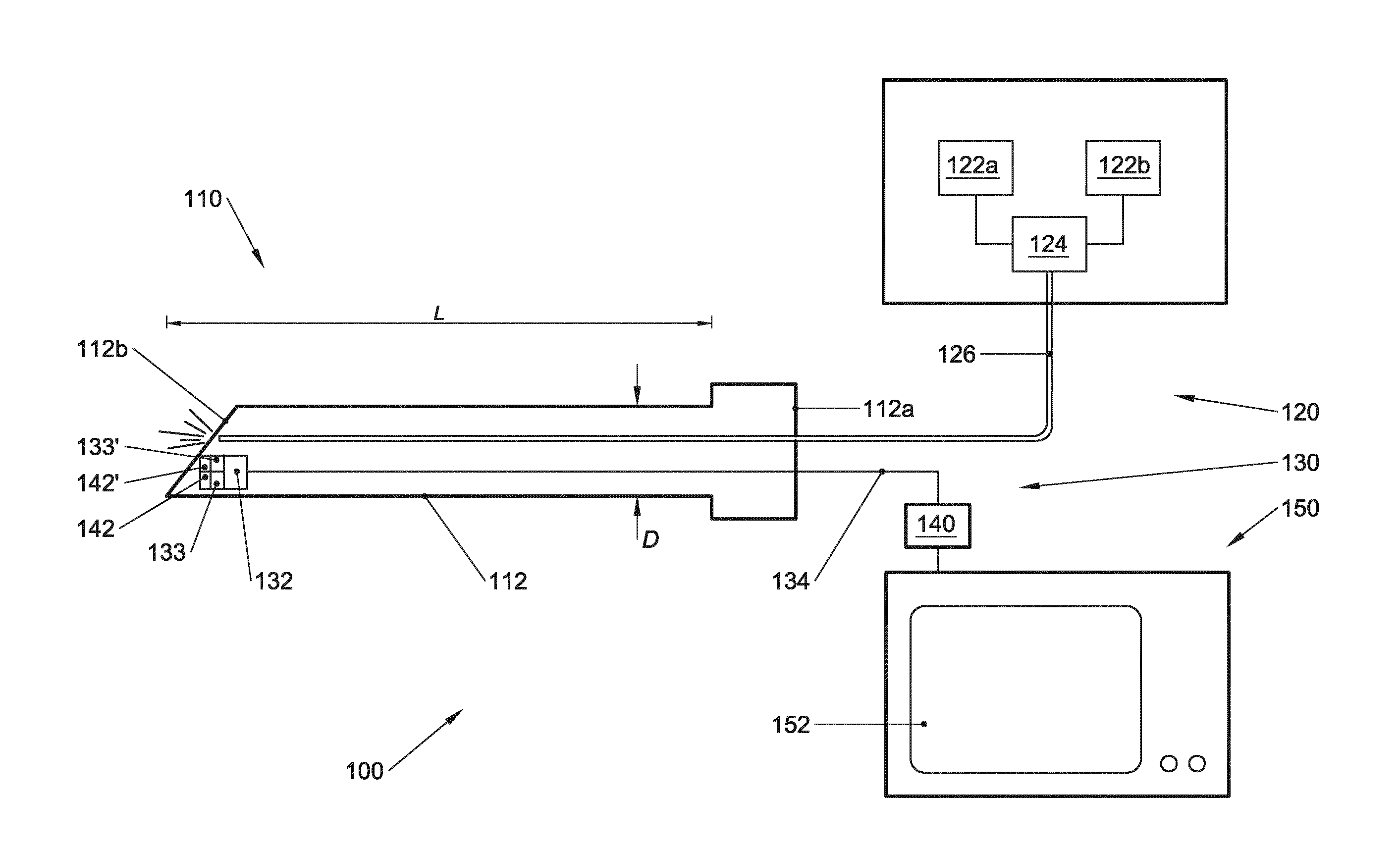
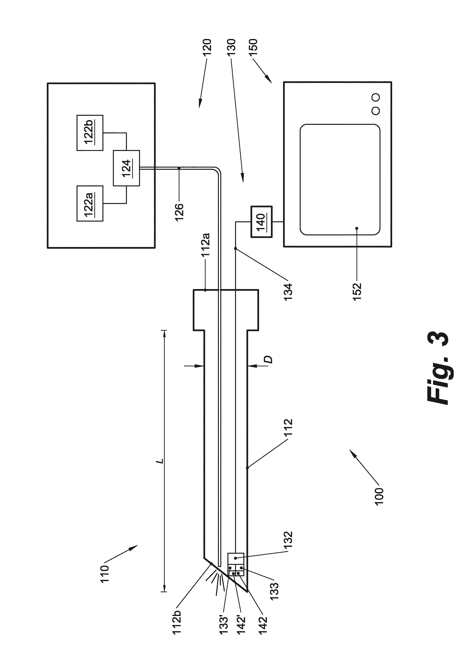
An arthroscopic instrument assembly (100), comprising: an illumination system (120) for illuminating an operative field, including a light source (122a) configured to produce light having at least one ligament excitation wavelength; an arthroscope (110); an image transmission system (130) configured to transmit a fluorescent image of the operative field at a distal end (112b) of the arthroscope (110) to an image viewing system (150); an image processing system (140) configured to process the fluorescent image as it passes through the image transmission system, so as to provide a false-color fluorescent image of the operative field in which a contrast between ligament and bone structures present in the operative field is enhanced relative to the unprocessed fluorescent image; and an image viewing system (150), operably connected to the image transmission system (130), and including a display (152) configured to enable viewing of the false-color fluorescent image.

Description

FIELD OF THE INVENTION[0001]The present invention relates to an arthroscopic instrument assembly, and to a method of localizing musculoskeletal tissue structures in a joint during arthroscopic surgery.BACKGROUND[0002]The anterior cruciate ligament (ACL) is the most commonly injured ligament of the knee. In cases where the injury involves a complete disruption of the ACL arthroscopic surgery may be required to reconstruct the ACL.[0003]During a surgical reconstruction, a torn ACL may be replaced by a graft, such as a tendon transplant, that is inserted into the knee. To fully restore the prior knee function without pain, instability and / or development of degenerative changes, it is of paramount importance that the graft is properly affixed to the tibia (shin bone) and the femur (thigh bone), in particular within the respective native attachment sites of the ACL. However, despite the fact that the anatomical position of the ACL has been geometrically described and charted relative to ...

Claims


Application Information

Patent Timeline
IPC IPC(8): A61B1/317A61B1/05A61B1/06A61B1/07A61B1/00A61B1/04
CPCA61B1/317A61B1/00045A61B1/043A61B1/0638A61B1/0676A61B1/05A61B1/00009A61B1/00011A61B1/07A61B1/0684A61B1/00078A61B5/0059A61B5/0071A61B5/0084
Inventor NGUYEN, DUY TANVAN LEEUWEN, TON GVAN HORSSEN, PEPIJN
Owner ACADEMISCH MEDISCH CENT BIJ DE UNIV VAN
Learn More