
Systems and methods for patterning using a laser

Inactive Publication Date: 2015-10-22
REVOLAZE LLC
View PDF33 Cites 36 Cited by
  • Summary
  • Abstract
  • Description
  • Claims
  • Application Information

AI Technical Summary

Benefits of technology

The present invention relates to systems and methods for generating patterns on fabrics using laser irradiation. The invention provides a way to decrease the size of the laser spot on a workpiece, which allows for higher resolution patterns. The method involves using a laser system with post-objective scanning architecture and larger mirrors than typically used in conventional laser systems. The laser system can be retrofitted into existing systems or combined with multiple lasers for larger field sizes. The invention also includes a method for irradiating the width of a fabric roll with a laser spot of about 0.55 mm or less. Overall, the invention provides a way to generate high-quality patterns on fabrics using lasers.

Problems solved by technology

However, certain standard available laser system can only achieve that spot size at a 500 mm field size.
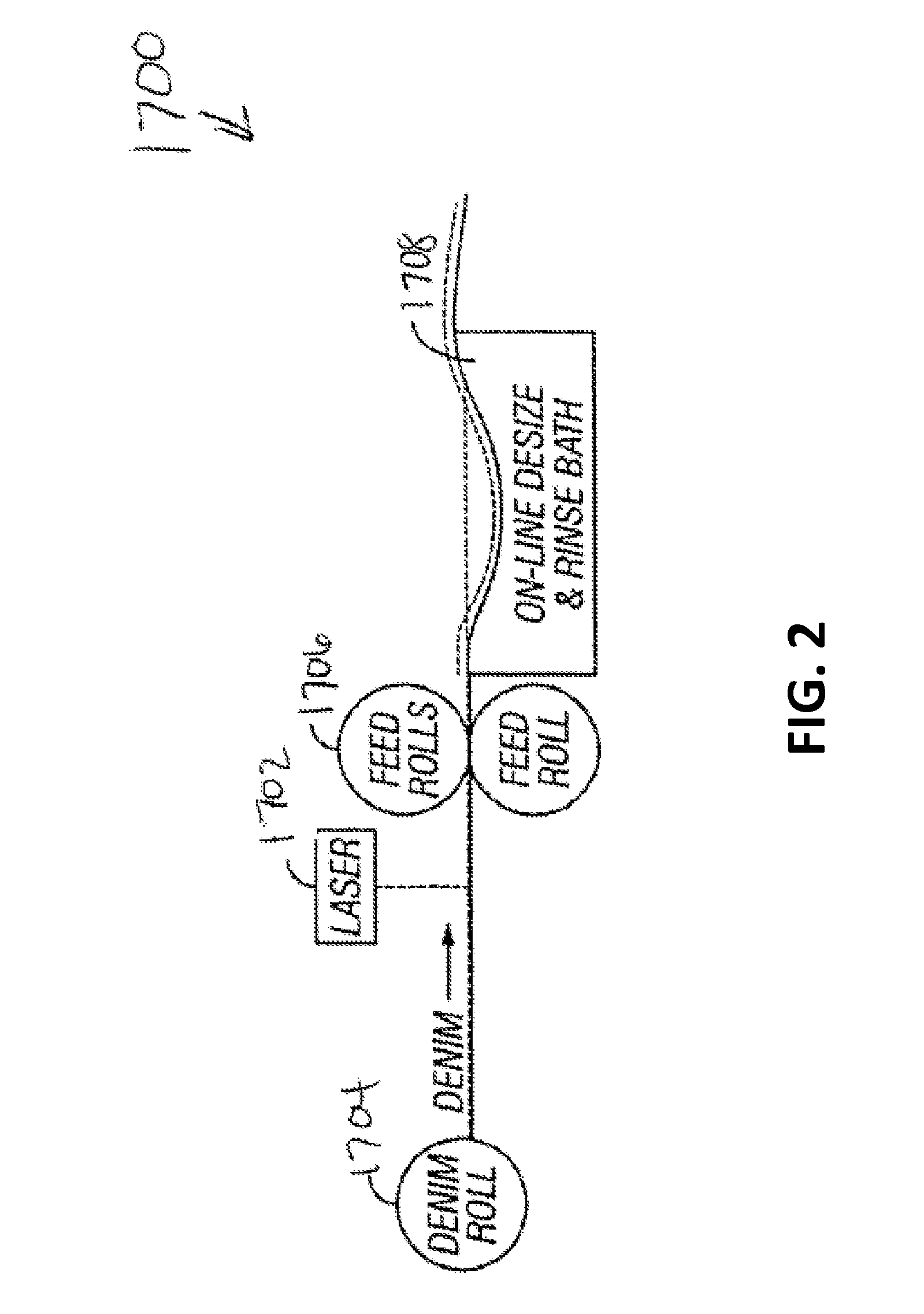
To use the same laser system to lase an 1800 mm field size, such as that of a denim roll, would produce a spot size much greater than 0.55 mm, which cannot generate sufficient fine resolution to create the desired fabric pattern.

Method used


Image

  • Systems and methods for patterning using a laser
  • Systems and methods for patterning using a laser
  • Systems and methods for patterning using a laser

Examples


Embodiment Construction

[0018]Reference will now be made in detail to exemplary embodiments and methods of the invention as illustrated in the accompanying drawings, in which like reference characters designate like or corresponding parts throughout the drawings. It should be noted, however, that the invention in its broader aspects is not limited to the specific details, representative devices and methods, and illustrative examples shown and described in connection with the exemplary embodiments and methods.

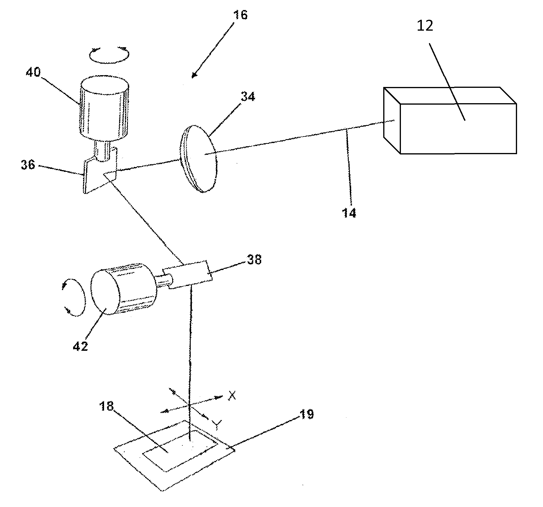
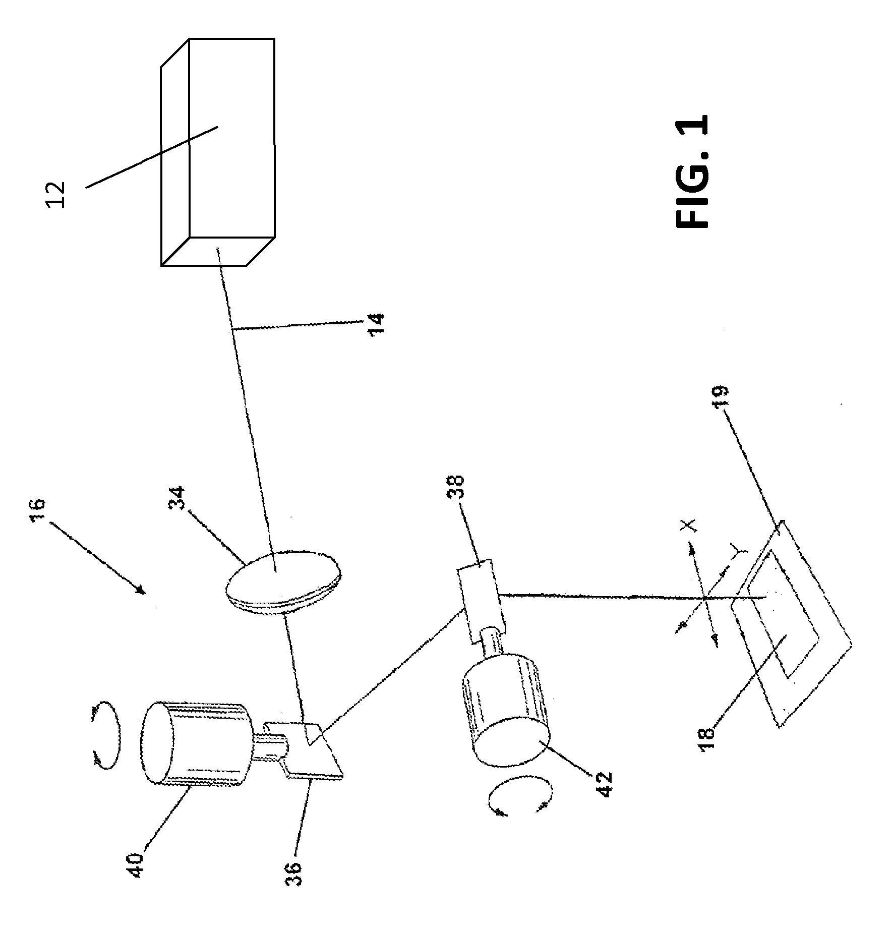
[0019]Exemplary embodiments of the present invention provide systems and methods for decreasing the spot size of a laser while operating the laser at a larger field size. Certain exemplary embodiments utilize a laser combined with a number of optical elements to form a high resolution image on a large substrate, where the laser spot size is smaller than that normally associated with a given laser field size. The system and methods are capable of providing higher resolution images over larger field size...


PUM

PropertyMeasurementUnit
Lengthaaaaaaaaaa
Lengthaaaaaaaaaa
Fractionaaaaaaaaaa

Abstract

The present invention generally relates to a surface treatment of fabric with a laser and, more specifically, to a system and method for generating a pattern used to process a surface of a fabric through laser irradiation and the fabric resulting from such treatment. The present invention provides small laser spot sizes while operating a laser at large field size by 1) using a laser system with post-objective scanning architecture; 2) using multiple lasers across the width of a fabric roll; and / or 3) increasing the size and weight of the laser scanning mirrors. The spot size normally associated with a smaller laser field size (e.g. 500 mm) may be achieved with a laser having a larger field size (e.g. 950 mm or greater) by practicing the teachings of this invention.

Description

CROSS-REFERENCE TO RELATED APPLICATION[0001]This application claims the benefit of priority to U.S. Provisional Application No. 61 / 981,250 filed on Apr. 18, 2014, the complete disclosure of which is incorporated herein by reference.FIELD OF THE INVENTION[0002]The present invention generally relates to surface treatment of fabric with a laser, and, more specifically, to systems and methods for generating a pattern on a fabric surface through laser irradiation, and to treated fabrics resulting from such treatment, especially denim fabric.BACKGROUND[0003]Fabrics, such as denim, can be processed to simulate a worn look. Conventionally, a wet process, such as a stone and / or enzyme process, is applied to the fabric, typically after the fabric has been transformed into a garment, to create a faded and worn look. Specifically, an enzyme wash in combination with an agitation element, such as stones or rocks, removes color from a ridged blue denim fabric to develop a contrasting pattern of va...

Claims


Application Information

Patent Timeline
IPC IPC(8): B23K26/00D06M10/00B23K26/073B23K26/06B23K26/02
CPCB23K26/0084B23K26/003D06M10/005B23K26/02B23K26/073B23K26/0643B23K26/082D06P5/15D06P5/2011B23K26/355
Inventor COSTIN, JR., DARRYL J.COSTIN, SR., DARRYL J.
Owner REVOLAZE LLC
Learn More