Control device for hybrid vehicle

a control device and hybrid technology, applied in the direction of machines/engines, process and machine control, instruments, etc., can solve the problems of inability to start the vehicle through ev travel, high cost, and driver's hesitation, so as to secure the controllability of the slip engagement state of the second clutch, reduce the revolving speed of the rotary electric machine, and reduce the load

Active Publication Date: 2015-10-22
AISIN AW CO LTD
View PDF10 Cites 16 Cited by
  • Summary
  • Abstract
  • Description
  • Claims
  • Application Information

AI Technical Summary

Benefits of technology

[0024]when reducing the target revolving speed, the rotary electric machine control means (23) reduces the target revolving speed (Nmtg) with a first predetermined gradient, and thereafter reduces the target revolving speed with a second predetermined gradient that is gentler than the first predetermined gradient.
[0025]Consequently, the revolving speed of the rotary electric machine can be reduced with the first predetermined gradient which is a steep gradient. Thus, it is possible to further reduce the load on the second clutch to be broug

Problems solved by technology

In the starting method according to Patent Document 1, however, the vehicle cannot be started through EV travel in the case where the battery remaining capacity is low.
Thus, it takes much time since the driver makes a starting request (such as turning off a brake or turning off an accelerator) until the

Method used


Image

  • Control device for hybrid vehicle
  • Control device for hybrid vehicle
  • Control device for hybrid vehicle

Examples


first embodiment

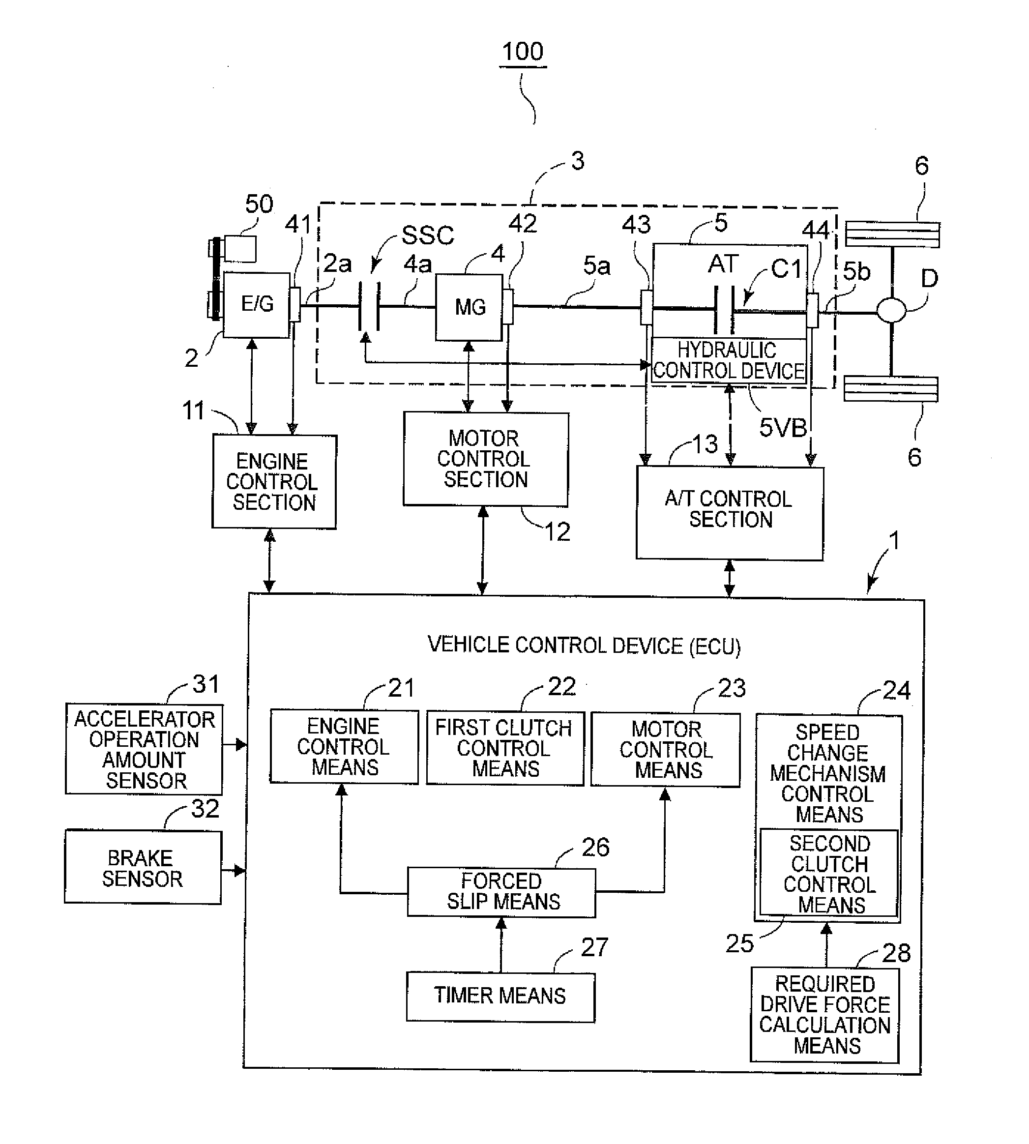
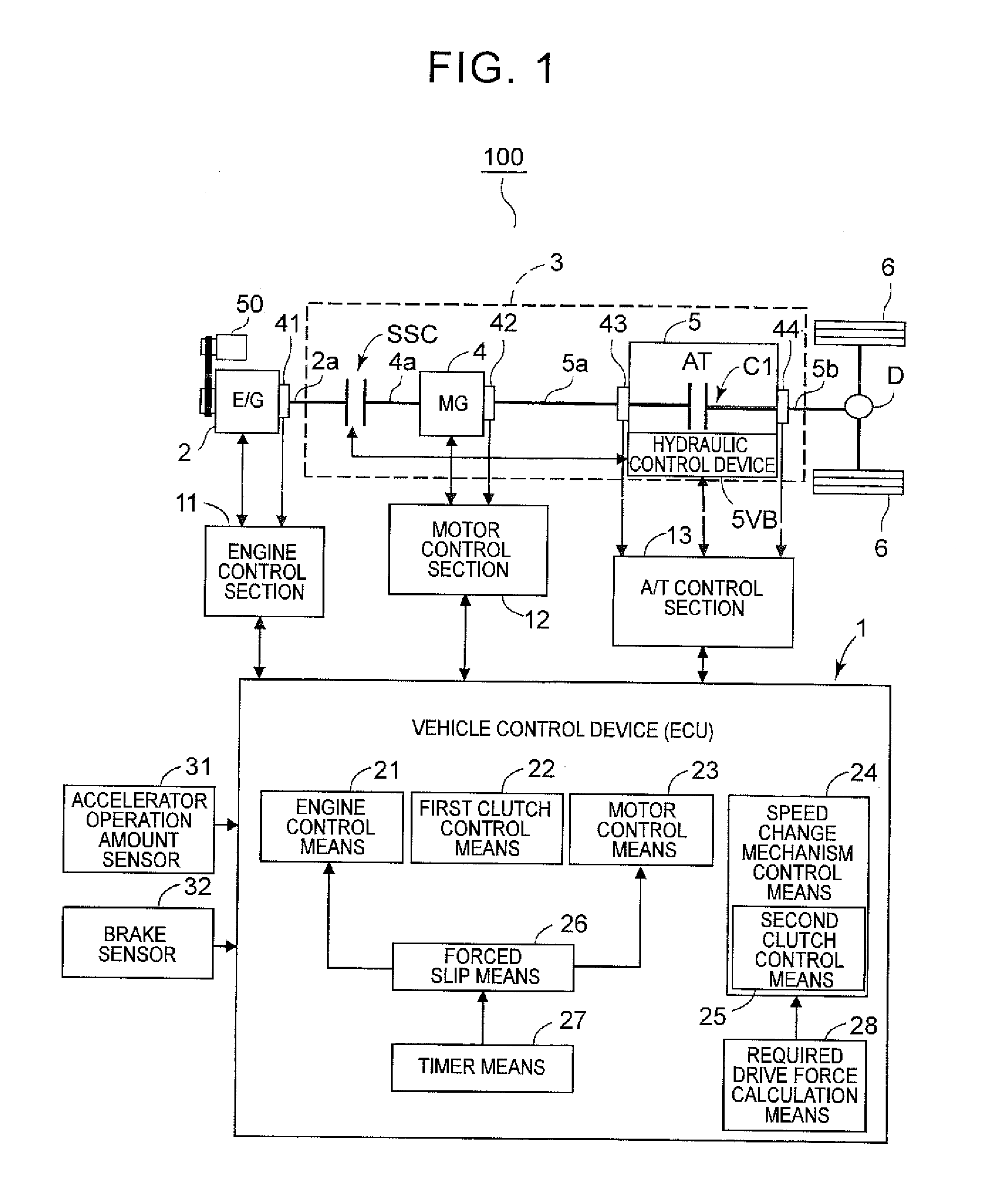
[0069]A first embodiment will be described below with reference to FIGS. 1 to 4. Forced slip means 26 and timer means 27 in FIG. 1 are provided for a second embodiment, and will not be described in relation to the first embodiment. Herein, the terms “rotational speed” and “revolving speed” are used as synonyms.

[0070]As illustrated in FIG. 1, a hybrid vehicle 100 includes, as its drive system, an engine 2 and a hybrid drive device 3 connected to an output shaft (crankshaft) 2a of the engine 2. An output shaft 5b of the hybrid drive device 3 is drivably coupled to a differential device D via a propeller shaft or the like. A drive force is transferred from the differential device D to left and right wheels 6 via left and right drive shafts or the like. In the hybrid vehicle 100, in addition, an alternator 50 capable of generating power through rotation of the engine 2 to supply electric power to an accessory (such as lamps and an air conditioner) is disposed to be drivably coupled to t...

second embodiment

[0122]Next, a second embodiment obtained by partially modifying the first embodiment will be described with reference to FIGS. 5 to 7. Portions of the hybrid vehicle 100 and the control device 1 that are the same as those of the first embodiment will not be described. In the following description, in addition, a case where the motor rotational speed Nm is reduced for forced slip control will first be described with reference to FIGS. 5 and 6, and a case where the engine rotational speed Ne is increased for the forced slip control will next be described with reference to FIG. 7 mainly with focus on differences from FIG. 6.

[0123]In the second embodiment, as illustrated in FIG. 1, the vehicle control device 1 includes the forced slip means 26 for forcibly causing the first clutch SSC to slip, and the timer means 27 for counting the time elapsed from the detection of a starting request (suspension of power generation control).

[0124]Next, control performed when the vehicle starts in the ...

third embodiment

[0158]Next, a third embodiment obtained by partially modifying the first embodiment will be described with reference to FIGS. 8 and 9. Portions of the hybrid vehicle 100 and the control device 1 that are the same as those of the first embodiment will not be described.

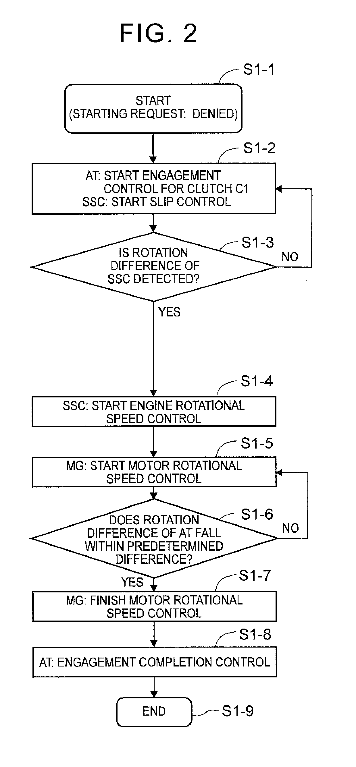
[0159]When the third embodiment is compared with the first embodiment, step S3-8 and step S3-9 are added as illustrated in FIG. 8, and slip that occurs when torque that is larger than the torque capacity of the second clutch C1 is transferred to the second clutch C1 is prevented for a predetermined time (first predetermined time) TB (that is, until the torque capacity of the second clutch C1 is sufficiently increased) from time t14 when a transition is made from the rotational speed control for the motor 4 to the torque control as illustrated in FIG. 9. Step S3-1 to step S3-7 illustrated in FIG. 8 correspond to step S1-1 to step S1-7, respectively, illustrated in FIG. 2. Step S3-10 and step S3-11 illustrated in FIG. 8 c...


PUM


Abstract

A control device for a hybrid vehicle for use in a hybrid vehicle in which a first clutch, a rotary electric machine, and a second clutch are disposed on a power transfer path from an engine to wheels sequentially from the engine side. After power generation control in which the engine is driven with the first clutch directly engaged and with the second clutch disengaged is suspended on the basis of detection of the starting request from a state in which the vehicle is stationary with the power generation control performed, the second clutch control means controls the second clutch from a disengaged state to a slip engagement state, the first clutch control means controls the first clutch from an engaged state to a slip engagement state, and the rotary electric machine control means reduces the target revolving speed.

Description

I. TECHNICAL FIELD[0001]Preferred embodiments relate to a control device for a hybrid vehicle in which a first clutch, a rotary electric machine, and a second clutch are disposed on a power transfer path from an engine to wheels sequentially from the engine side, and specifically relates to a control device for a hybrid vehicle that suspends power generation control and starts the vehicle when a starting request is detected during power generation control in which the rotary electric machine is driven by the engine.BACKGROUND ART[0002]In recent years, there has been developed a hybrid vehicle of a so-called one-motor parallel type that includes an engine, a motor / generator (hereinafter referred to simply as “motor”), an engine connection clutch interposed between the engine and the motor, and a speed change mechanism that has a clutch capable of enabling and disabling power transfer between the engine and the motor and wheels (see Patent Document 1 and Patent Document 2, for example...

Claims


Application Information

Patent Timeline
IPC IPC(8): B60W20/00B60W10/08B60W10/06B60W10/02B60L50/16
CPCB60W20/40B60W10/02B60W10/08B60W10/06Y10S903/93B60W2710/021B60W2710/025B60W2710/0644B60W2710/081B60W2540/00B60K6/48B60K6/547B60W20/00B60W30/18027B60W30/18054F02D29/06B60K2006/4825B60Y2300/429Y02T10/62B60W20/13B60W2540/10B60W2540/12B60L15/20B60L2210/40B60L2240/12B60L2240/421B60L2240/423B60L2240/441B60L2240/443B60L2240/486B60L2240/507B60L2260/26B60L50/16Y02T10/64Y02T10/72Y02T10/7072Y02T10/70B60K6/38B60K6/40B60W10/04
Inventor ONOUCHI, TOMOHIROTSUDA, KOHEI
Owner AISIN AW CO LTD
Why Eureka
Try Eureka