Catalytic Heating Assembly for an Oil Storage Tank

Active Publication Date: 2015-10-22
ENVIRO PRODN SYST INC +1
View PDF10 Cites 5 Cited by
  • Summary
  • Abstract
  • Description
  • Claims
  • Application Information

AI Technical Summary

Benefits of technology

The patent describes a heater casing that is placed in an oil storage tank to transfer heat directly from a catalytic heater to the surrounding oil. This casing is much more efficient and takes up less space than traditional heat exchangers. Additionally, it is much stronger and can withstand abrasive sand and corrosive fluids better, making maintenance a lot easier.

Problems solved by technology

Although the heat exchanger fluid can effectively heat the contents of the oil storage tank, the heat exchanger coil in the storage tank can be difficult to maintain as it is subjected to abrasive sands and corrosive fluids within the oil storage tank.
Furthermore, considerable heat may be lost in communication between the remotely located catalytic heater and the heater coil in the oil storage tank.

Method used


Image

  • Catalytic Heating Assembly for an Oil Storage Tank
  • Catalytic Heating Assembly for an Oil Storage Tank
  • Catalytic Heating Assembly for an Oil Storage Tank

Examples


Embodiment Construction

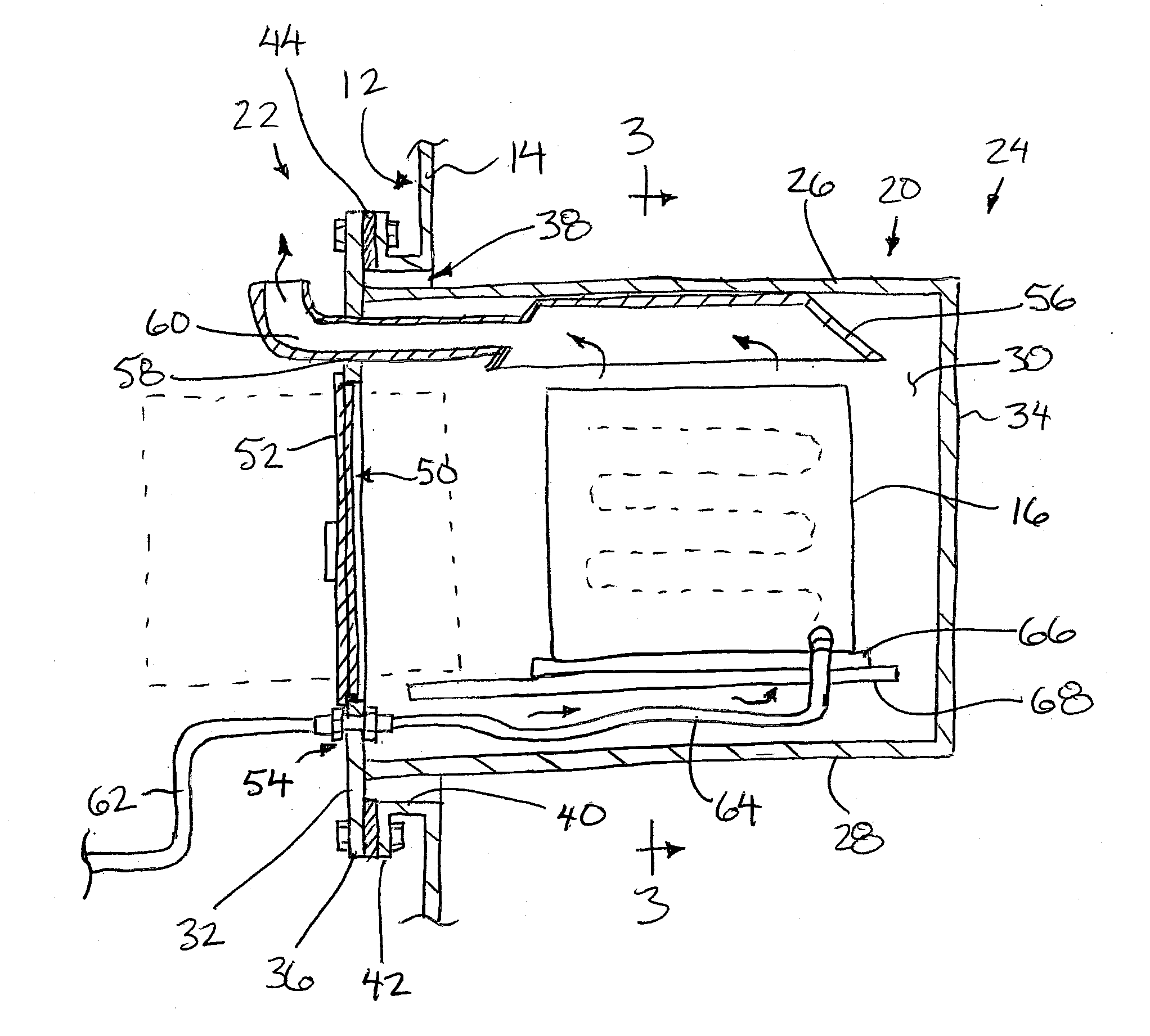
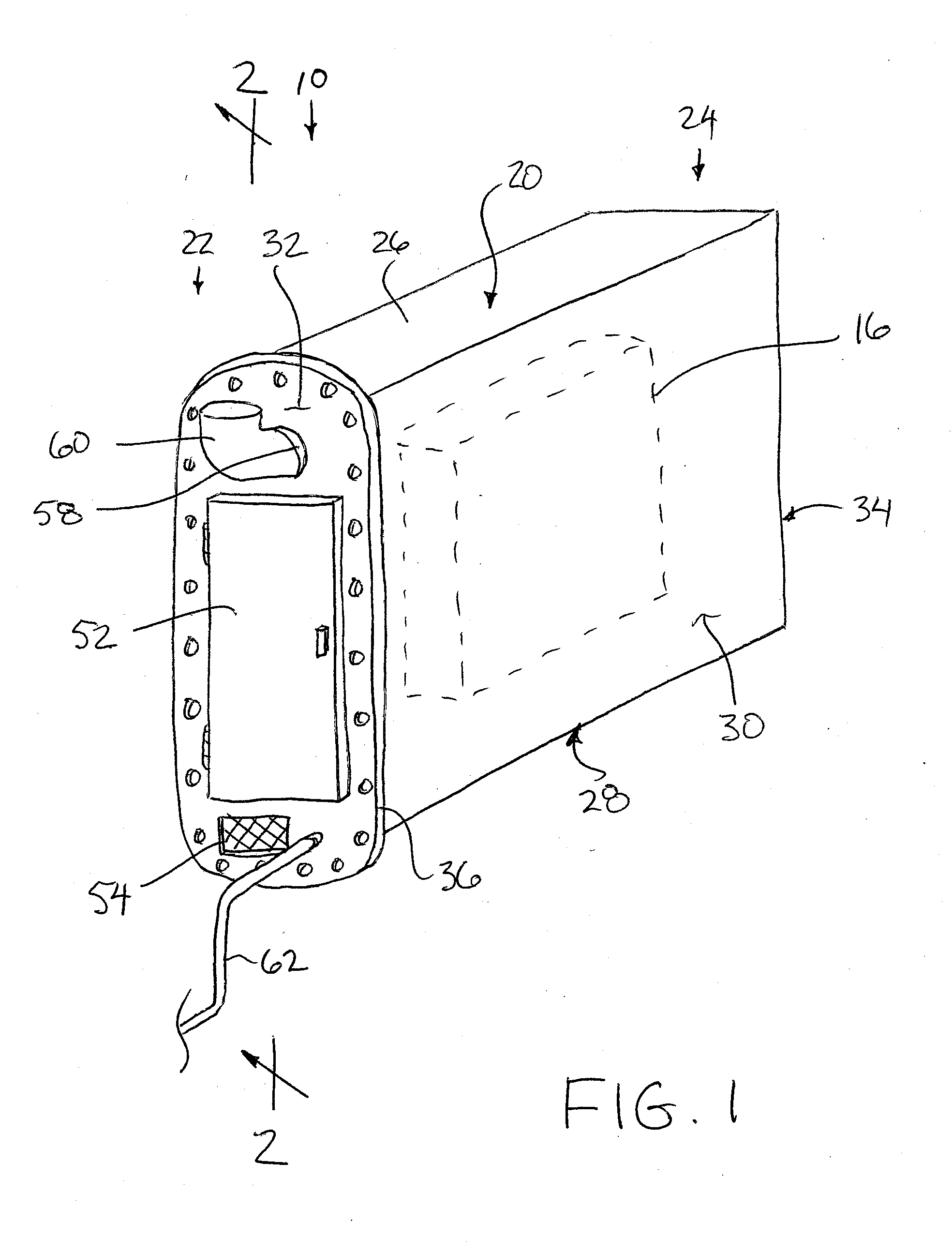
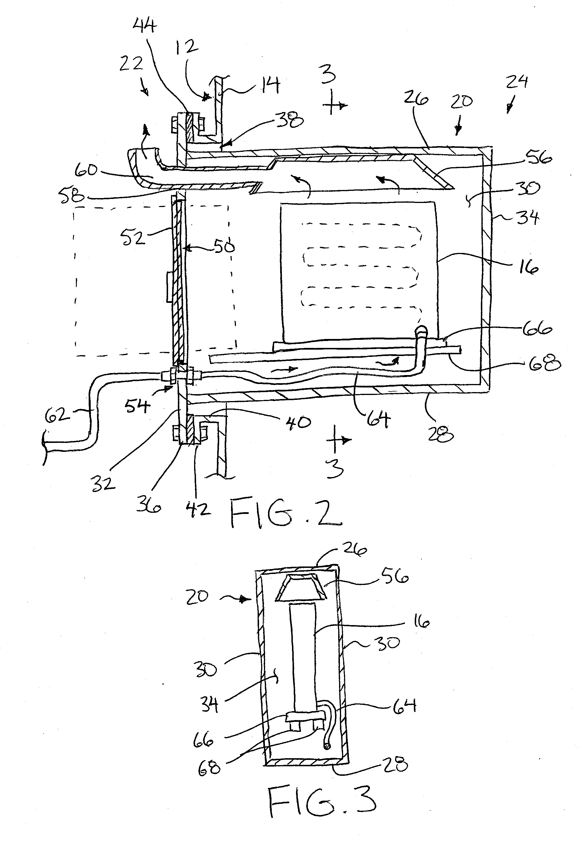
[0036]Referring to the accompanying figures, there is illustrated a heating assembly generally indicated by reference numeral 10. The assembly 10 is suited for heating a liquid storage tank 12 having tank boundary walls 14 surrounding the hollow interior which defines a main liquid storage portion for storing liquid, for example oil therein. The heating assembly 10 is used with a hydrocarbon fuelled flameless catalytic heater unit 16.

[0037]The heater unit 16 in a conventional catalytic heater unit, for example of the type available under the trademark name Catadyne. A typical heater unit relies on a flameless combustion or oxidation of a gaseous hydrocarbon fuel, for example natural gas or propane fed by a fuel supply line, in order to produce heat. The heater unit typically includes a respective housing which contains a catalyst pad having a catalyst carried on a substrate to provide a catalyst bed upon which the fuel is combusted. The combustion is an exothermic oxidation reaction...


PUM


Abstract

In an oil storage tank having an interior oil storage chamber and a tank opening in one of the boundary walls, a heating assembly is supported to extend into the interior oil storage chamber from the tank opening. The assembly includes a casing of walls surrounding with a casing mounting flange mountable in sealing engagement relative to a tank mounting flange about the full perimeter of the tank opening such that the casing protrudes into the interior oil storage chamber of the oil storage tank. The heating chamber is suitable sized and configured to operably receive a catalytic heater therein. The heating chamber further accommodates entry of combustion air and combustion fuel into the heating chamber and exhaust of emissions therefrom.

Description

[0001]This application claims the benefit under 35 U.S.C. 119(e) of U.S. provisional application Ser. No. 61 / 980,882, filed Apr. 17, 2014.FIELD OF THE INVENTION[0002]The present invention relates to a heating assembly arranged to be received in a storage tank, for example an oil storage tank, in which the heating assembly comprises a heating chamber received within an interior of the storage tank and which in turn receives a catalytic heating unit therein.BACKGROUND[0003]In oil production, it is common to locate an oil storage tank at an oil well site to produce hydrocarbons from the well directly into the oil storage tank. It is also known to provide a propane burner which directs exhaust into a burner tube extending into the oil storage tank for heating oil in the tank to maintain fluidity and / or prevent freezing of contents within the tank. Heating the oil may also assist in settling sand out of the oil to the bottom of the tank, and assists with fluidity of the oil when subseque...

Claims


Application Information

Patent Timeline
IPC IPC(8): B65D88/74F24H1/20
CPCB65D88/744B65D88/748F24H1/206F24H9/1836
Inventor THIESSEN, LESTER JAMES
Owner ENVIRO PRODN SYST INC
Why Eureka
Try Eureka