A Straight Fin Tube with Bended Fins Condensing Heat Exchanger

a heat exchanger and straight fin technology, applied in indirect heat exchangers, water heaters, lighting and heating equipment, etc., can solve the problems of reducing heat exchanging efficiency, condensing boilers can not only use sensible heat in the flue but also latent heat, and high flue temperature of conventional boilers

Inactive Publication Date: 2015-10-22
SUZHOU CQ HEAT EXCHANGER
View PDF4 Cites 6 Cited by
  • Summary
  • Abstract
  • Description
  • Claims
  • Application Information

AI Technical Summary

Benefits of technology

[0015]An embodiment of the present invention pertains to a forced convection fin tube condensing heat exchanger for supplying heat. The forced convection fin tube condensing heat exchanger includes a shell, a burner, a group of fin tubes in the shell, a water inlet, a water outlet, a flue outlet on the shell, and a connector between the burner and air/gas mixture. The burner is under the shell. A set of fin tubes are installed around the burner tightly and coaxially. The flue channel is formed by the shell and a row of fin tubes below the burner. The flue gas flows along the flue channel to flue outlet. There are front water manifold and back water manifold at the two ends of the fin tubes. The water baffles inside the rear water manifold divide the rear water manifold into water inlet area and outlet area. The water en...

Problems solved by technology

The conventional boiler has very high flue temperature because of the limitation of the structure.
However, condensing boiler can not only use sensible heat in the flue but also the latent heat because of the low flue temperature.
It decreases the heat exchanging efficiency.
The heat exchanger is not designed to absorb the sensible and latent heat when the water vapor condensing, and there is no condensate.
The life the condensing boiler will be shortened significantly if the carbon steel or cast iron i...

Method used


Image

  • A Straight Fin Tube with Bended Fins Condensing Heat Exchanger
  • A Straight Fin Tube with Bended Fins Condensing Heat Exchanger
  • A Straight Fin Tube with Bended Fins Condensing Heat Exchanger

Examples


Embodiment Construction

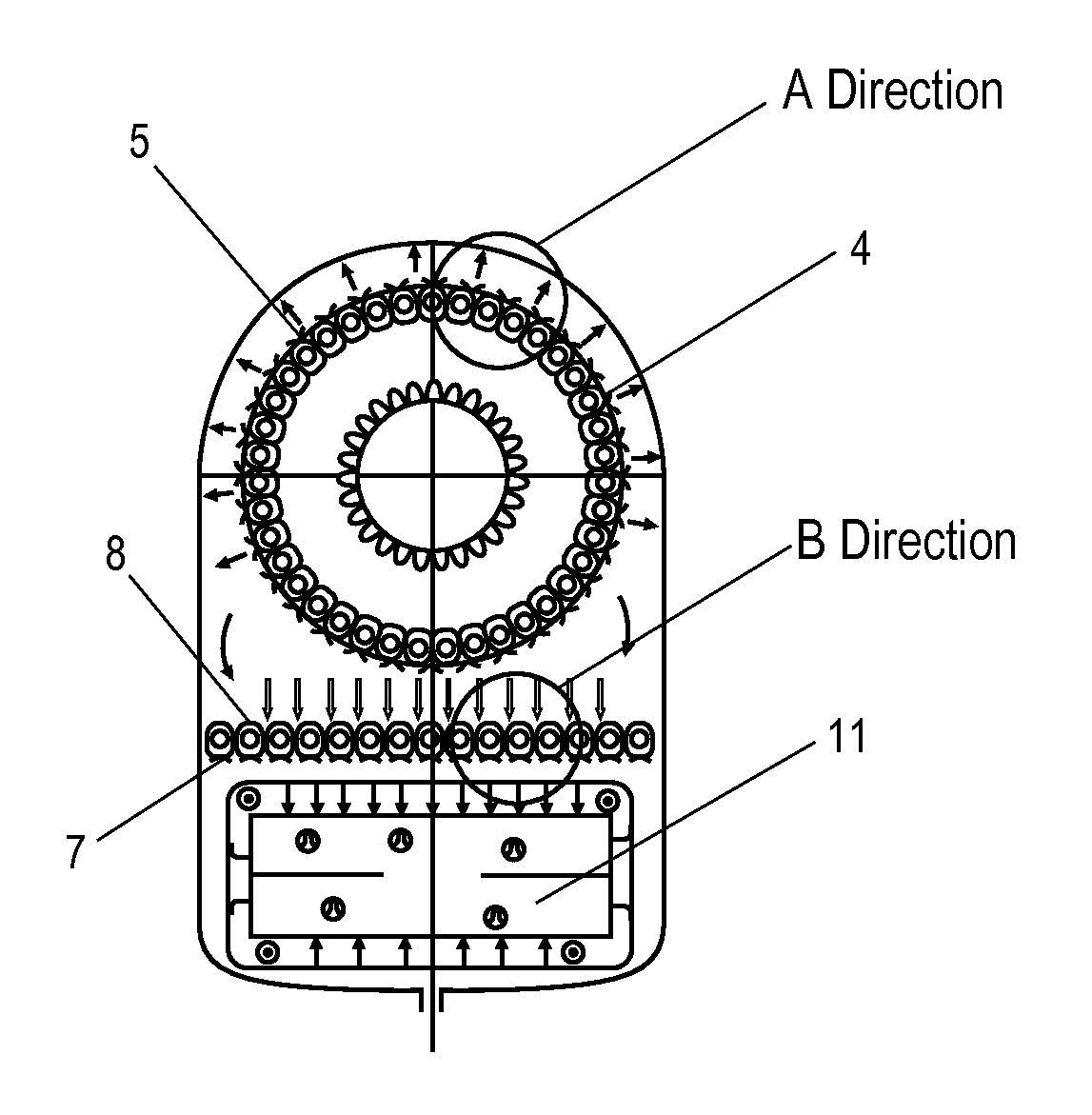
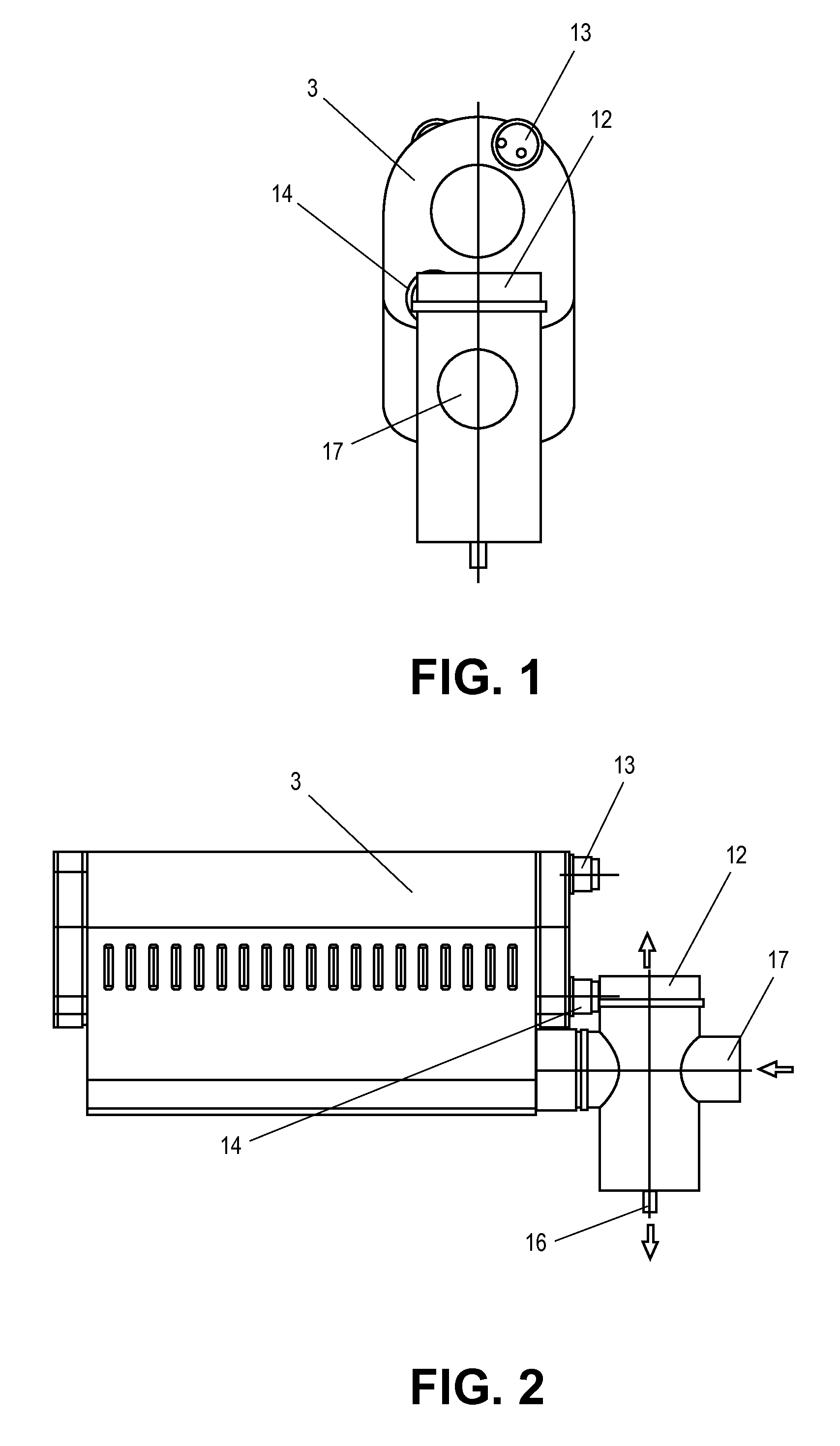
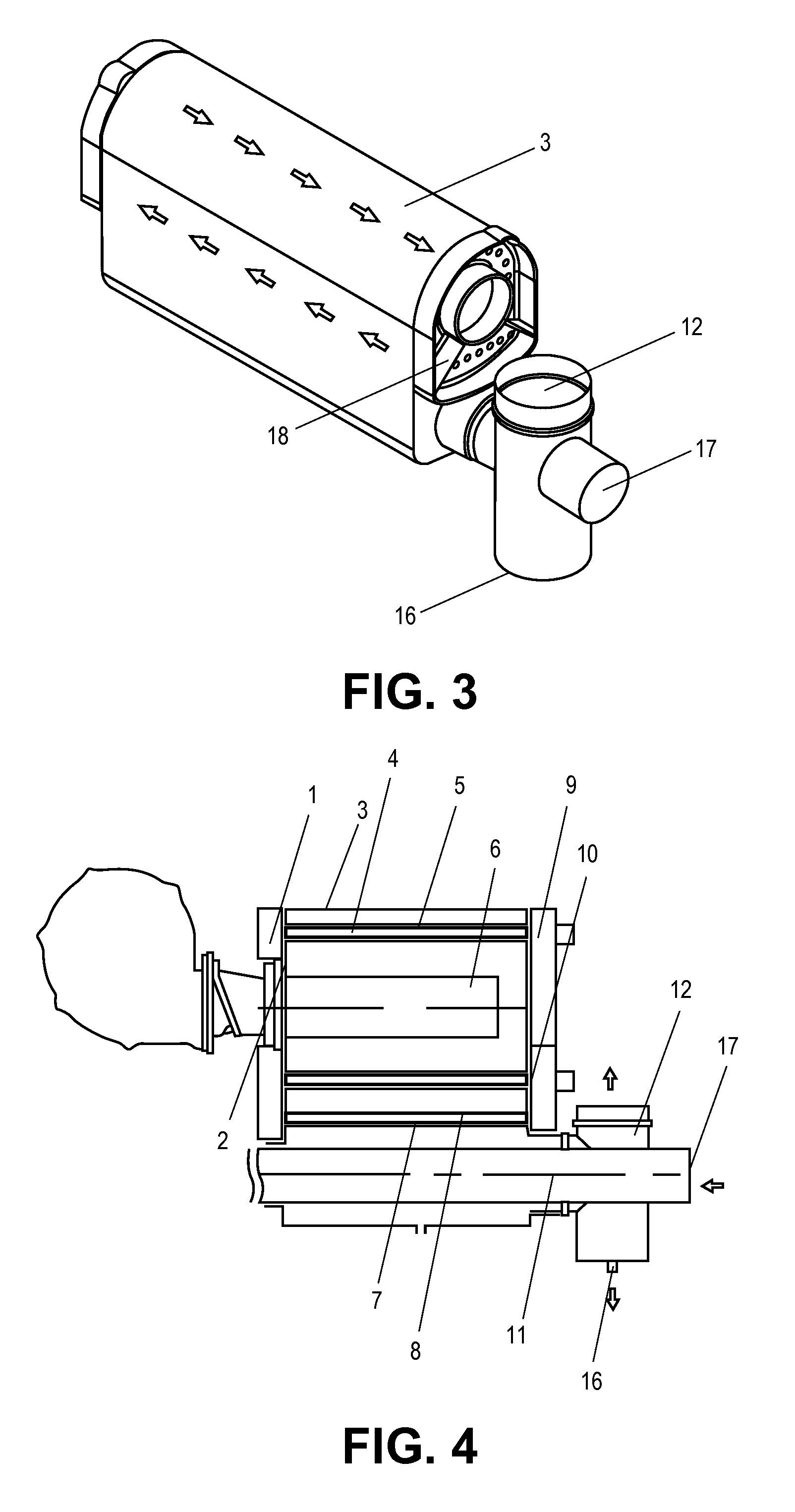
[0044]Various embodiments of the present invention provide for an improved heat exchanger that is configured to provide greater efficiency. In some embodiments, the integral structure layout is able to increase the heat exchanger efficiency. In some aspects the heat exchanger has a counter flow design with two-stage heat exchanger. The burner is on the top and the flue outlet on the bottom. After burning, the combustion flue gas flows through the group of fin tubes around the burner and flue baffles located outside these tubes first, then it flows through the row of fin tubes above the flue channel and the flue baffles under these tubes. And then the flue gas flows out from the flue outlet along the flue channel and counter flow with inlet air. The water inlet is close to the flue outlet at the bottom, and the water outlet is on the top of the heat exchanger. The water flows through inlet, fin tubes, and the cavities connected to the upper and lower fin tube bundles at both ends, su...


PUM


Abstract

A forced convection fin tube condensing heat exchanger for supplying heat includes a shell, burner and fin tubes bundle. The burner is at the top of the shell, circular fin tubes bundle installed around the burner tightly, circularly and coaxially. The flue channel which is formed by the shell and a row of fin tubes bundle is below the burner. The flue flows along the flue channel to flue outlet. There are front and rear water manifolds at the two ends of the fin tubes. Water baffles inside the rear water manifold divide the rear water manifold into water inlet and outlet areas. The water enters the small portion of circular fin tubes bundle from water inlet area, through the front water manifold, back to the water outlet area via the main portion of the circular fin tubes bundle. The use of bended fin tube to improves efficiency.

Description

CROSS REFERENCE TO RELATED APPLICATIONS[0001]This application is a national stage application and claims priority to PCT / CN2013 / 083871, filed on Sep. 21, 2013, which claims priority to CN 201210353552.1, filed on Sep. 21, 2012, the disclosures of which are incorporated herein by reference in their entireties.FIELD OF THE INVENTION[0002]This invention relates generally to equipment in the heating industry field. More particularly, the invention is related to a forced convection straight fin tube condensing heat exchanger for supplying heat.BACKGROUND OF THE INVENTION[0003]As far back as the Middle East oil crisis in the in 20th century, to save the energy, the high efficient condensing boiler was developed in Europe. The outstanding feature of the boiler is that the efficiency is 10% higher than the conventional boiler. Abundant water vapor in the flue is condensed and releases the latent heat of vaporization because the flue temperature can be decreased to below the dew point. This ...

Claims


Application Information

Patent Timeline
IPC IPC(8): F24H8/00F24H3/08
CPCF24H3/087F24H8/006F24H1/403F24H1/406F24H1/445F24H9/0084Y02B30/00
Inventor CUI, SHUQING
Owner SUZHOU CQ HEAT EXCHANGER
Why Eureka
Try Eureka