Counterflow helical heat exchanger

Inactive Publication Date: 2015-10-22
ENTEREX AMERICA
View PDF13 Cites 14 Cited by
  • Summary
  • Abstract
  • Description
  • Claims
  • Application Information

AI Technical Summary

Benefits of technology

The present invention aims to provide an improved heat exchanger assembly that can offer equivalent or better heat transfer performance in a smaller package. Additionally, it also increases the flow path length for a given tube length, resulting in more efficient heat transfer. Furthermore, this invention allows for counterflow operation, optimizing heat transfer performance.

Problems solved by technology

Increasing the flow path length of the fluids while maintaining reasonable fluid pressure drops is another approach to increased heat transfer, but it is not usually possible to accomplish this in a smaller space.

Method used


Image

  • Counterflow helical heat exchanger
  • Counterflow helical heat exchanger
  • Counterflow helical heat exchanger

Examples


Embodiment Construction

)

[0038]In describing the embodiment of the present invention, reference will be made herein to FIGS. 1-9 of the drawings in which like numerals refer to like features of the invention.

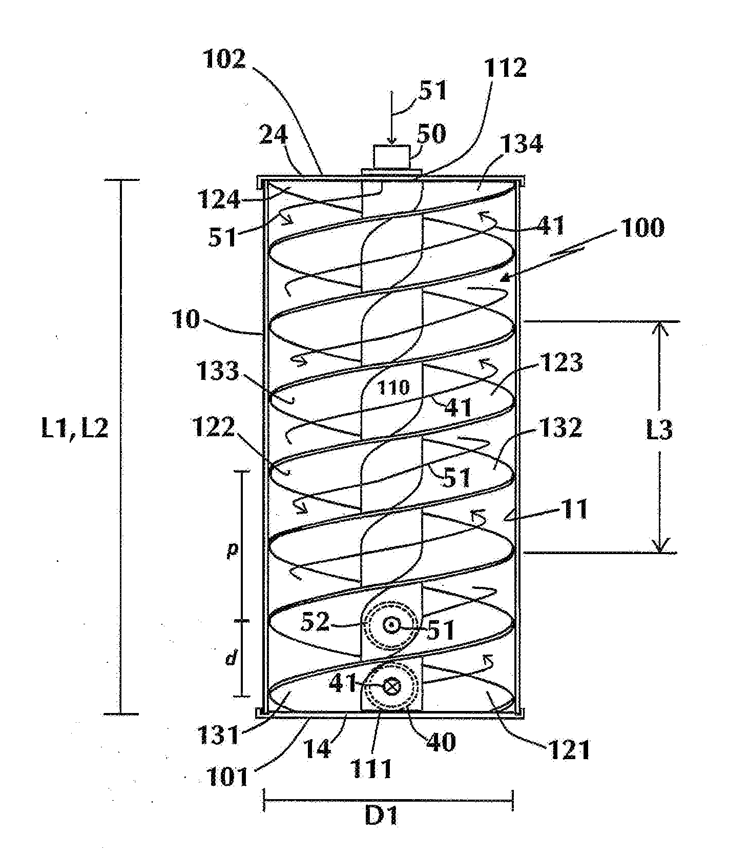
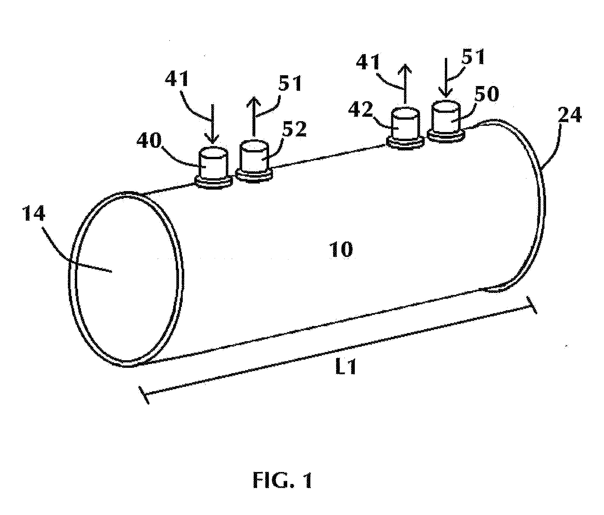
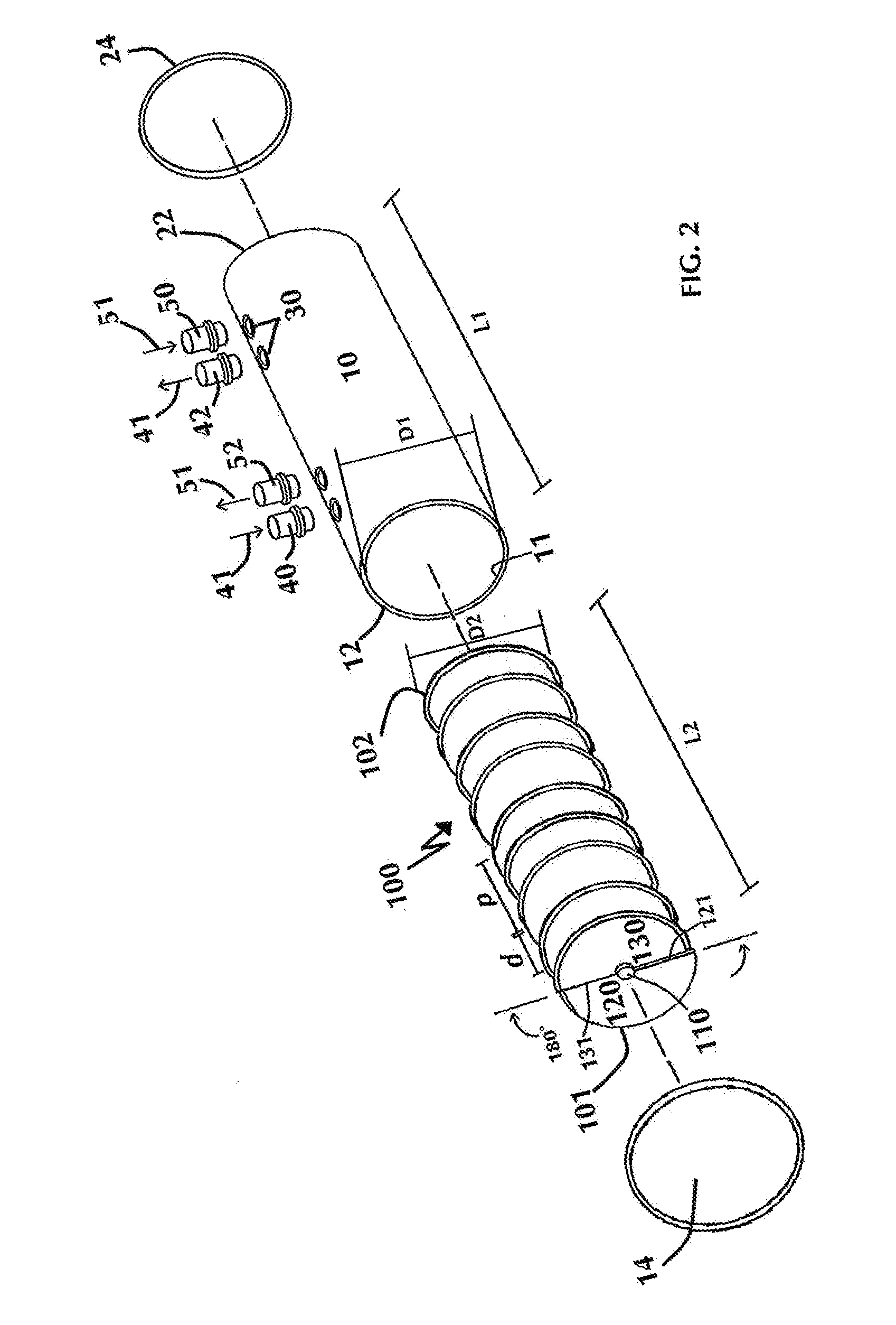
[0039]The present invention is directed to a heat exchanger assembly including a heat exchanger tube and a helical tube insert. The helical tube insert is sealed within a tube of substantially similar cross-section, thereby creating two distinct fluid flow paths within the tube. The pitch of the helical convolutions is less than or equal to the inner diameter of the tube, in order to obtain fluid flow paths of increased length over that of a conventional liquid-to-liquid heat exchanger tube. The ends of the heat exchanger tube are capped and the tube is fitted with inlet and outlet fluid ports for each of the two fluid flow paths. The flow paths within the heat exchanger assembly of the present invention may be parallel flow or co-current (where the fluids move in the same direction), or counterflow (w...


PUM

PropertyMeasurementUnit
Angleaaaaaaaaaa
Lengthaaaaaaaaaa
Flow rateaaaaaaaaaa

Abstract

A heat exchanger assembly comprising a tube with a thermally conductive tube insert sealed therein, the tube insert having a substantially similar cross-section to the cross-section of the tube, and a plurality of fluid ports for passage of fluid into and out of the tube, the fluid ports arranged for counterflow operation. The tube insert includes a pair of helices extending along the length of the tube insert, the helices having first and second sides offset from each other by a predetermined distance along the length of the tube insert and first and second ends, each of the first ends offset from the other by a predetermined angle and each of the second ends offset from the other by a predetermined angle. The tube insert is sealed within the tube to form a first fluid flow path and a second fluid flow path, the first fluid flow path defined between the first sides of the helices and the second fluid path defined between the second sides of the helices.

Description

RELATED APPLICATIONS[0001]This application claims priority to U.S. Application No. 61 / 980,274, filed on Apr. 16, 2014.BACKGROUND OF THE INVENTION[0002]1. Field of the Invention[0003]The present invention relates to heat exchangers and, more particularly, to liquid-to-liquid heat exchangers for use in comparatively smaller spaces, such as in automobiles or other motor vehicles.[0004]2. Description of Related Art[0005]Designers of heat exchangers for use in automobiles and other motor vehicles are constantly striving to obtain increased heat transfer capability in a smaller space. In the field of liquid-to-liquid heat exchangers, the use of turbulators on the hot fluid side and extended surface, such as a sintered metal matrix, on the cool fluid side, are well-known approaches to the problem. Increasing the flow path length of the fluids while maintaining reasonable fluid pressure drops is another approach to increased heat transfer, but it is not usually possible to accomplish this i...

Claims


Application Information

Patent Timeline
IPC IPC(8): F28D7/10B23P15/26F28F1/36
CPCF28D7/10B23P15/26F28F1/36F28D7/022F28F9/24F28D7/026F28F13/12F28D7/0066F28F1/022F28F9/0202F28F2009/0287F28F2230/00F28F2275/04F28F2275/122
Inventor KOLB, JAMES
Owner ENTEREX AMERICA
Why Eureka
Try Eureka