Regulation circuit associated with synchronous rectifier providing cable compensation for the power converter and method thereof

a technology of synchronous rectifiers and power converters, applied in the direction of electric variable regulation, process and machine control, instruments, etc., can solve problems such as significant power loss, and achieve the effect of reducing power loss

Inactive Publication Date: 2015-10-22
SEMICON COMPONENTS IND LLC
View PDF1 Cites 29 Cited by
  • Summary
  • Abstract
  • Description
  • Claims
  • Application Information

AI Technical Summary

Benefits of technology

The present invention is a regulation circuit and method for a power converter that compensates for output voltage to reduce power loss and improve efficiency. This is achieved without using a shunt resistor to sense the output current.

Problems solved by technology

However, it will generate a significant power loss while sensing the output current by using a shunt resistor.

Method used


Image

  • Regulation circuit associated with synchronous rectifier providing cable compensation for the power converter and method thereof
  • Regulation circuit associated with synchronous rectifier providing cable compensation for the power converter and method thereof
  • Regulation circuit associated with synchronous rectifier providing cable compensation for the power converter and method thereof

Examples


Embodiment Construction

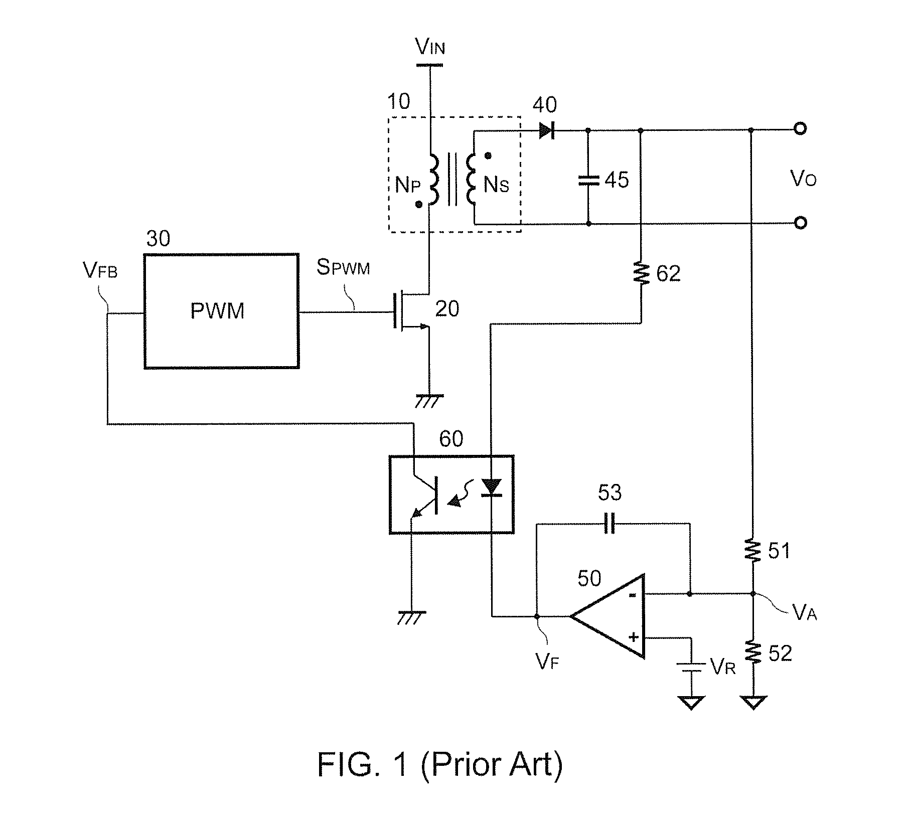
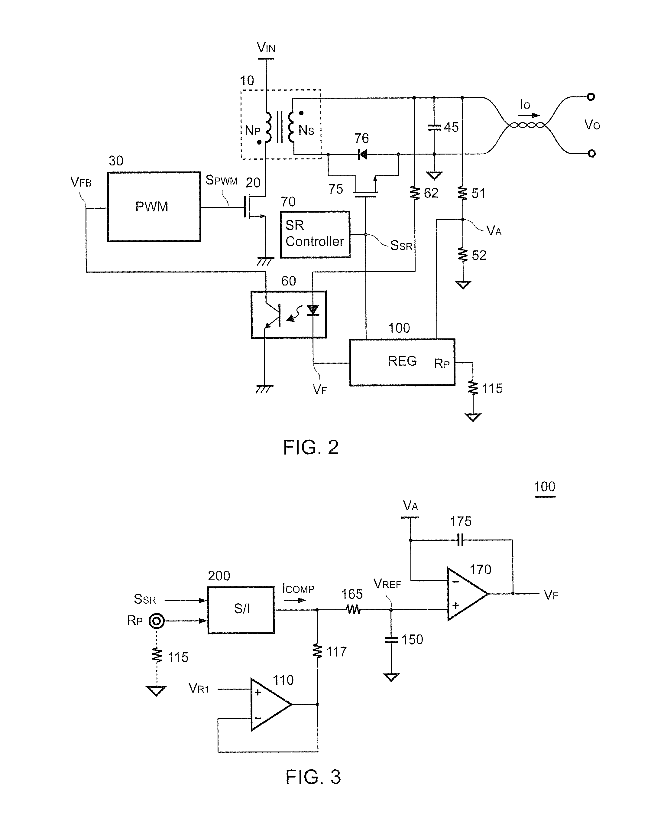
[0017]FIG. 2 is a circuit diagram of a preferred embodiment of the power converter having a regulation circuit 100 according to the present invention. The power converter comprises the transformer 10, the power transistor 20, the PWM controller (PWM) 30, the opto-coupler 60, a synchronous rectifying (SR) controller 70, a power transistor 75, and the regulation circuit (REG) 100. The power transistor 20 is coupled from the primary winding NP of the transformer 10 to the ground for switching the transformer 10. The PWM controller 30 generates the switching signal SPWM to switch the power transistor 20 in accordance with the fee dback signal VFB for regulating the output (output voltage VO and / or the output current IO) of the power converter.

[0018]The opto-coupler 60 is coupled to the secondary winding NS of the transformer 10 through the resistor 62. The opto-coupler 60 generates the feedback signal VFB coupled to the PWM controller 30 in response to the output voltage VO. The seconda...


PUM


Abstract

A regulation circuit of a power converter for cable compensation according to the present invention comprises a signal generator generating a compensation signal in accordance with a synchronous rectifying signal. An error amplifier has a reference signal for generating a feedback signal in accordance with an output voltage of the power converter. The compensation signal is coupled to program the reference signal. The feedback signal is coupled to generate a switching signal for regulating an output of the power converter. The regulation circuit of the present invention compensates the output voltage without a shunt resistor to sense the output current of the power converter for reducing power loss.

Description

REFERENCE TO RELATED APPLICATION[0001]This reference is being filed as a Continuation Application of patent application Ser. No. 13 / 551,705, filed 18 Jul. 2012, currently pending.BACKGROUND OF THE INVENTION[0002]1. Field of the Invention[0003]The present invention is related to a regulation circuit, especially to a regulation circuit associated with a synchronous rectifier providing cable compensation for the power converter.[0004]2. Description of the Related Art[0005]FIG. 1 shows a prior art of a power converter. A PWM controller (PWM) 30 generates a switching signal SPWM to switch a transformer 10 having a primary winding NP and a secondary winding NS via a power transistor 20 in accordance with a feedback signal VFB for regulating the output of the power converter. The primary winding NP of the transformer 10 is coupled to receive an input voltage VIN. The feedback signal VFB is generated by an opto-coupler 60 in response to the output voltage VO of the power converter. The opto...

Claims


Application Information

Patent Timeline
Patent Type & Authority Applications(United States)
IPC IPC(8): G05F1/575
CPCG05F1/575H02M3/33592H02M1/0025Y02B70/10
Inventor YANG, TA-YUNGWANG, CHOU-SHENG
Owner SEMICON COMPONENTS IND LLC
Why Eureka
Try Eureka