Method and apparatus for measuring quality parameters of optical transmission channel

a technology of optical transmission channel and quality parameter, applied in the field of communication technologies, can solve the problems of inapplicability of methods, inability to measure in service, and inability to accurately measure actual ase noise power, and achieve the effect of saving network operation and maintenance and facilitating network operation and maintenan

Active Publication Date: 2015-10-22
LUSTER LIGHTWAVE CO LTD
View PDF5 Cites 22 Cited by
  • Summary
  • Abstract
  • Description
  • Claims
  • Application Information

AI Technical Summary

Benefits of technology

[0018]By the method according to an embodiment of the present invention, the issues of real-time measurement of various key performance parameters of the 40 Gbps, 100 Gbps and beyond-100 Gbps coherent polarization-multip...

Problems solved by technology

1) In the non-coherent 40 Gbps and coherent 100 Gbps systems, the signal bandwidth exceeds the channel grid (i.e. 50 GHz) of dense wavelength division multiplexing system defined by International Telecommunications Union (ITU). The spectra of adjacent DWDM channels overlap with each other, thus the ASE noise in the middle between neighboring DWDM channels is shielded by the signal. Therefore, the actual ASE noise power cannot be measured accurately by the traditional OSA based noise interpolation method.
2) Although such an issue may be solved by the signal ON-OFF method, it needs to interrupt the service during the measurement, and thus an in-service measurement is impossible.
3) The polarization extinction method can solve the above...

Method used


Image

  • Method and apparatus for measuring quality parameters of optical transmission channel
  • Method and apparatus for measuring quality parameters of optical transmission channel
  • Method and apparatus for measuring quality parameters of optical transmission channel

Examples


Embodiment Construction

[0034]The embodiments of the invention will be described in detail below, and examples of the embodiments will be shown in the drawings, in which the same or similar elements or elements with the same or similar functions will be represented by the same or similar labels throughout. The embodiments described below with reference to the drawings are exemplary for explaining the invention only, rather than being construed as limiting the invention.

[0035]In the description of the invention, it should be understood that, terms “first” and “second” are only used for the purpose of description, rather than being construed as indicating or implying relative importance or implying the number of technical features indicated. Thereby, the features defined by “first” or “second” may explicitly or implicitly include one or more such features. In the description of the invention, unless otherwise defined explicitly and specifically, the term “a plurality of” means two or more.

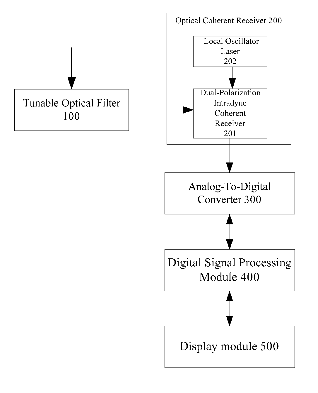
[0036]FIG. 1 is an ...


PUM


Abstract

The present invention discloses a method and an apparatus for measuring quality parameters of optical transmission channels. The apparatus comprises: a tunable optical filter for receiving an optical signal, performing wavelength or optical carrier demultiplexing on the optical signal, and out-of-band ASE noise suppression; an optical coherent receiver connected to the tunable optical filter, for performing polarization- and phase-diversity detection on the filtered optical signal and converting it into multiple lane baseband electrical signals; analog-to-digital converters for sampling and quantizing the multiple lane baseband electrical signals so as to convert the them into multiple lane digital signals; a digital signal processing module for processing the multiple lane digital signals to obtain quality parameters; and an display module for displaying the quality parameters. By the device according to an embodiment of the invention, real-time measurement of various key performance parameters of the 40 Gbps, 100 Gbps and extra-100 Gbps (for example, 200 Gbps, 400 Gbps and 1 Tbps) coherent polarization-multiplexed system is achieved simultaneously, especially the issue of real-time measurement of the in-service in-band OSNR is solved. Therefore, the network operation and maintenance are facilitated and the cost of network operation and maintenance is saved.

Description

FIELD OF THE INVENTION[0001]The present invention relates to a field of communication technologies, and in particular, to a method and a device for measuring quality parameters of optical transmission channels.BACKGROUND OF THE INVENTION[0002]Optical communications is entering an era of coherent detection. The 40 Gbps polarization-multiplexed binary (differential) phase shift keying (PM-(D) BPSK) and the 40 Gbps and 100 Gbps polarization-multiplexed quadrature (differential) phase shift keying (PM-(RZ) (D)QPSK) technologies are being deployed commercially. The coherent communication technology will be indispensable for future 200 Gbps, 400 Gbps and even 1 Tbps transmission systems. Presently, the 40 Gbps and 100 Gbps coherent systems are still in an initial deployment stage, and more and more coherent systems will be deployed in the dense wavelength division multiplexing (DWDM) networks. For the network operation and maintenance, the operator needs to monitor the in-service performa...

Claims


Application Information

Patent Timeline
IPC IPC(8): H04B10/079H04B10/2507
CPCH04B10/2507H04B10/0795H04B10/07951H04B10/07953
Inventor LIU, WEIQIANGZHAO, YONGPENG
Owner LUSTER LIGHTWAVE CO LTD
Why Eureka
Try Eureka