System and method for processing navigational sensor data

a technology of navigation sensor and processing method, which is applied in the field of interventional or surgical navigation system, can solve the problems of system sensitive to calibration errors, calibration drift, and the increase in the noise of the measurement generated by such sensors

Inactive Publication Date: 2015-10-29
GENERAL ELECTRIC CO
View PDF21 Cites 17 Cited by
  • Summary
  • Abstract
  • Description
  • Claims
  • Application Information

AI Technical Summary

Benefits of technology

[0004]In one embodiment, a surgical or interventional navigation system is provided. The surgical or interventional navigation system includes a transmitter assembly having at least a first transmitter coil and a second transmitter coil and a sensor assembly having one or more sensor components defining a plane. The surgical or interventional navigation system also includes an electromagnetic tracking system in communication with both the transmitter assembly and the sensor assembly. The electromagnetic tracking system is configured to: acquire a plurality of measurements using the sensor assembly, wherein each measurement corresponds to a projection of a three-dimensional vector onto the plane; and to determine one or both of an orientation and a position of the sensor assembly based on the polar coordinates of the measurements.
[0005]In a further embodiment, a surgical or interventional navigation system is provided. The surgical or interventional navigation system includes a transmitter assembly having at least a first transmitter coil and a second transmitter coil and a sensor assembly having one or more sensor components defining a plane. The sensor assembly is configured to generate measurements corresponding to position and orientation of the sensor assembly within electromagnetic fields generated by the transmitter assembly. The surgical or interventional navigation system also includes an electromagnetic tracking system in communication with both the transmitter assembly and the sensor assembly. The electromagnetic tracking system is configured to: drive the first transmitter coil at a first frequency and the second transmitter coil at a second frequency when the sensor assembly is within a one or more of a threshold distance, field strength, or field orientation relative to both the first transmitter coil and the second transmitter coil; and to drive the first transmitter coil in a multiplexed manner at the first frequency and at the second frequency and not drive the second transmitter coil when the sensor assembly is within the threshold distance, field strength, or field orientation relative to the first transmitter coil and outside the threshold distance, field strength, or field orientation relative to the second transmitter coil.
[0006]In an additional embodiment, a surgical or interventional navigation system is provided. The surgical or interventional navigation system includes a display, a transmitter assembly having at least a first transmitter coil and a second transmitter coil; and a sensor assembly having one or more sensor components defining a plane. The sensor assembly is configured to generate measurements corresponding to position and orientation of the sensor assembly within electromagnetic fields generated by the transmitter assembly. The surgical or interventional navigation system also includes an electromagnetic tracking system in communication with the transmitter assembly, the sensor assembly, and the display. The electromagnetic tracking system is configured to provide feedback comprising user instructions via the display. The feedback is based on the position and orientation of the sensor assembly within a navigable volume defined by the transmitter assembly and on the expected noise characteristics at the position and orientation.

Problems solved by technology

However, such systems may be sensitive to calibration errors as well as to calibration drift over time.
Further the measurements generated by such sensors may be increasingly noisy as the distance between the sensor and the source of the electromagnetic fields (typically one or more electromagnetic transmission coils) increases.

Method used


Image

  • System and method for processing navigational sensor data
  • System and method for processing navigational sensor data
  • System and method for processing navigational sensor data

Examples


Embodiment Construction

[0016]Various approaches are discussed herein for improving the processing algorithms, and systems implementing such algorithms, used in determining position and orientation information for a medical navigation system. By way of example, in one implementation the criterion that is minimized as part of the position and orientation determination is essentially independent of local electromagnetic field strength, thereby making the minimization operation independent of field strength calibration. Alternatively, such an approach may also allow for field strength calibration, including auto-calibration of the navigation sensor. In addition, noise performance of the navigation system may be improved by the approaches discussed herein.

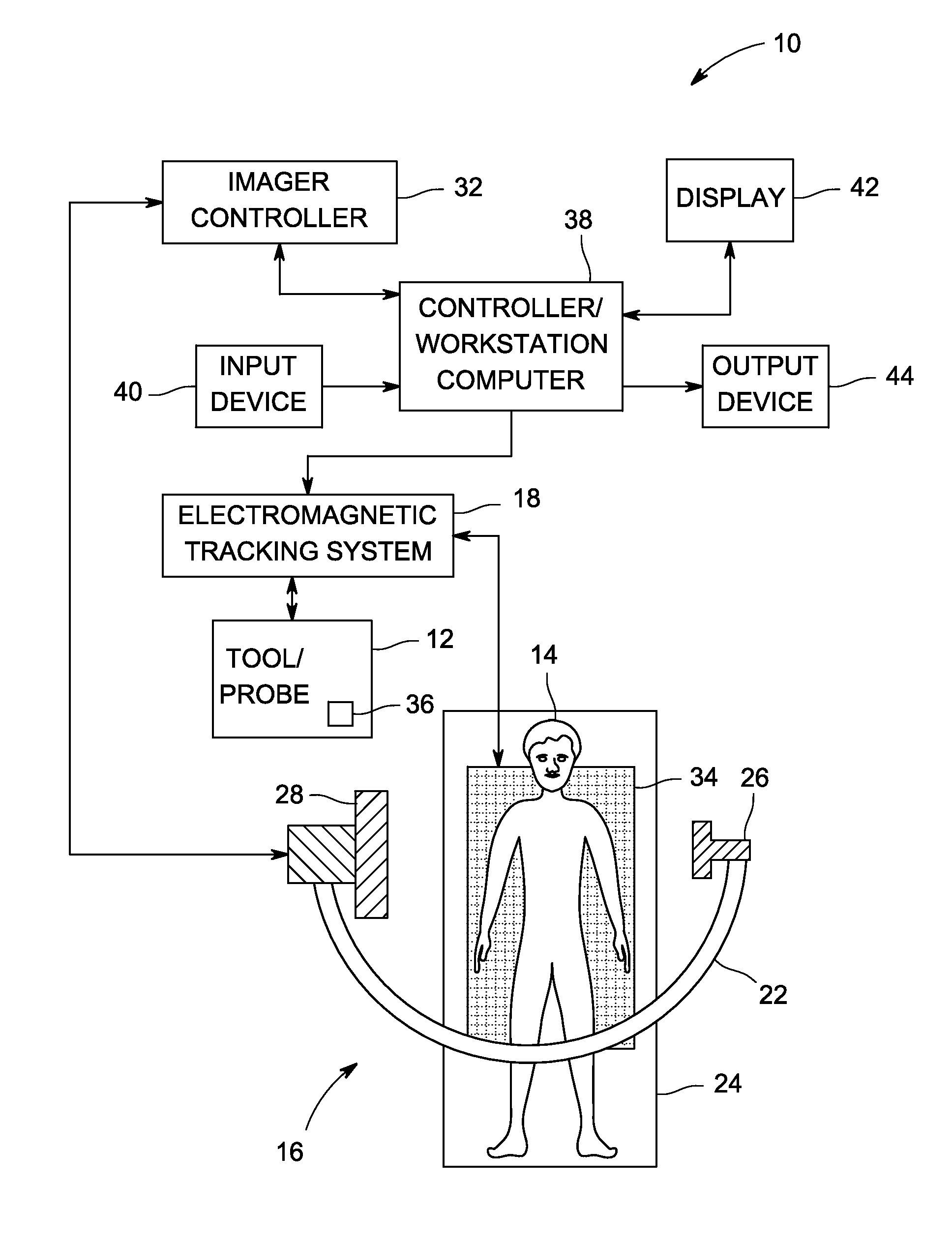
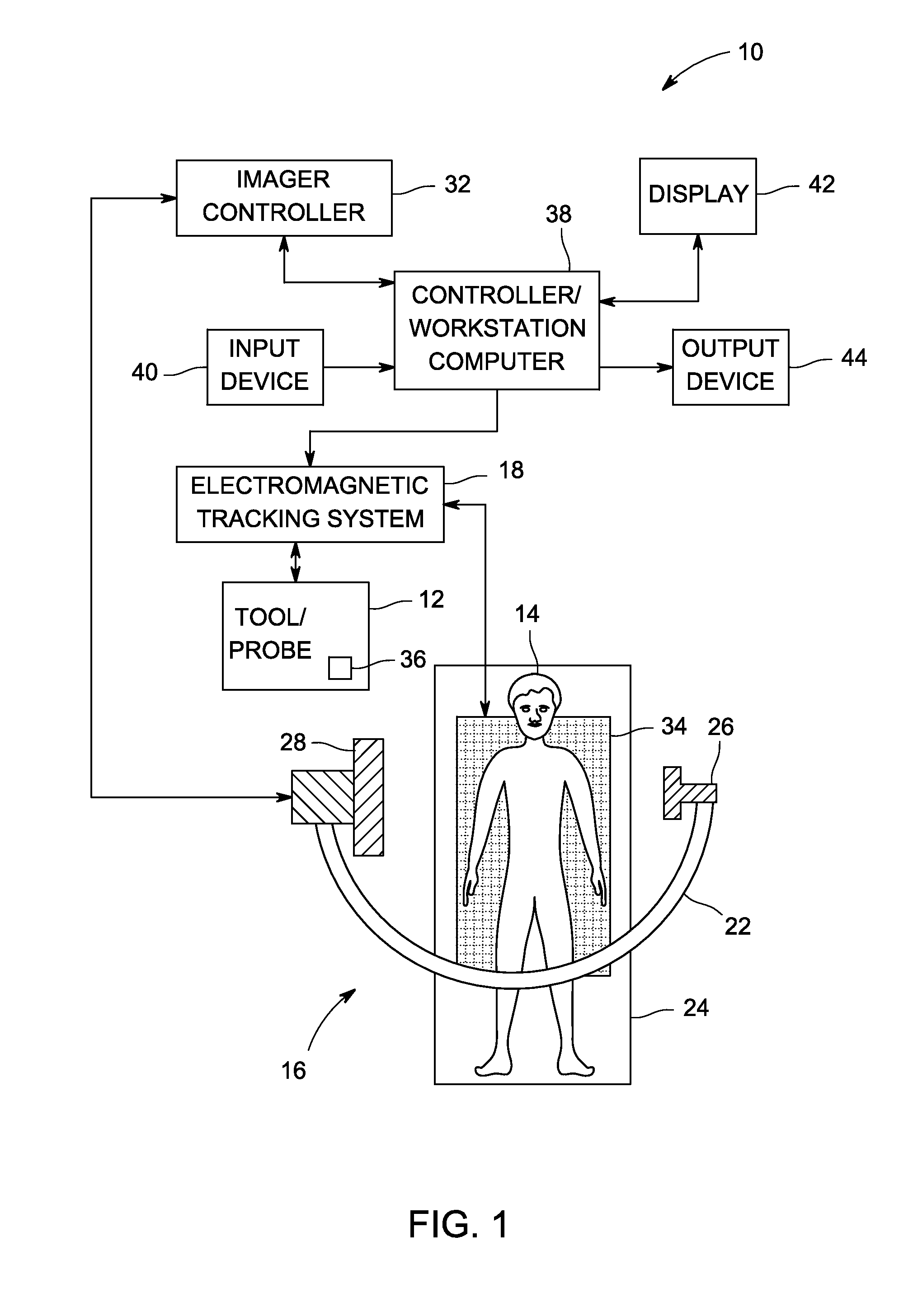
[0017]With the preceding in mind, FIG. 1 illustrates an embodiment of a navigation system 10 suitable for tracking movement of a surgical or interventional tool or object 12 (e.g., a catheter, a laparoscope, and so forth) with respect to a patient 14. In the ...


PUM


Abstract

Aspects of the present disclosure relate to approaches for determining position and orientation of a tracked tool in a medical navigational context. In one embodiment, the position of a surgical or interventional tool may be determined using the orientation or field direction data such that the determination is independent of field strength or magnitude. Feedback may be provided to a user based on these determinations. In certain embodiments, the navigational system may be auto-calibrated using position information determined independent of field strength or magnitude.

Description

BACKGROUND[0001]The subject matter disclosed herein relates generally to an interventional or surgical navigation system that may be used to provide position and orientation information for an instrument, implant or device used in a medical context, such as in a surgical or interventional context.[0002]In various medical contexts it may be desirable to acquire position and / or orientation information for a medical instrument, implant or device that is navigated or positioned (externally or internally) relative to a patient. For example, in surgical and / or interventional contexts, it may be useful to acquire position and / or orientation information for a medical device when the device, or a relevant portion of the device, is out of view, such as within a patient's body. Likewise, in certain procedures where an imaging technique is used to observe all or part of an interventional or surgical procedure, it may be useful to have position and orientation information derived from the tracke...

Claims


Application Information

Patent Timeline
Patent Type & Authority Applications(United States)
IPC IPC(8): A61B19/00A61B5/06G01B7/00
CPCA61B19/5244A61B2019/5251A61B5/061G01B7/003A61B34/20A61B2090/376A61B2034/2051
Inventor CLAUS, BERNHARD ERICH HERMANN
Owner GENERAL ELECTRIC CO
Why Eureka
Try Eureka