Control of a gas turbine engine

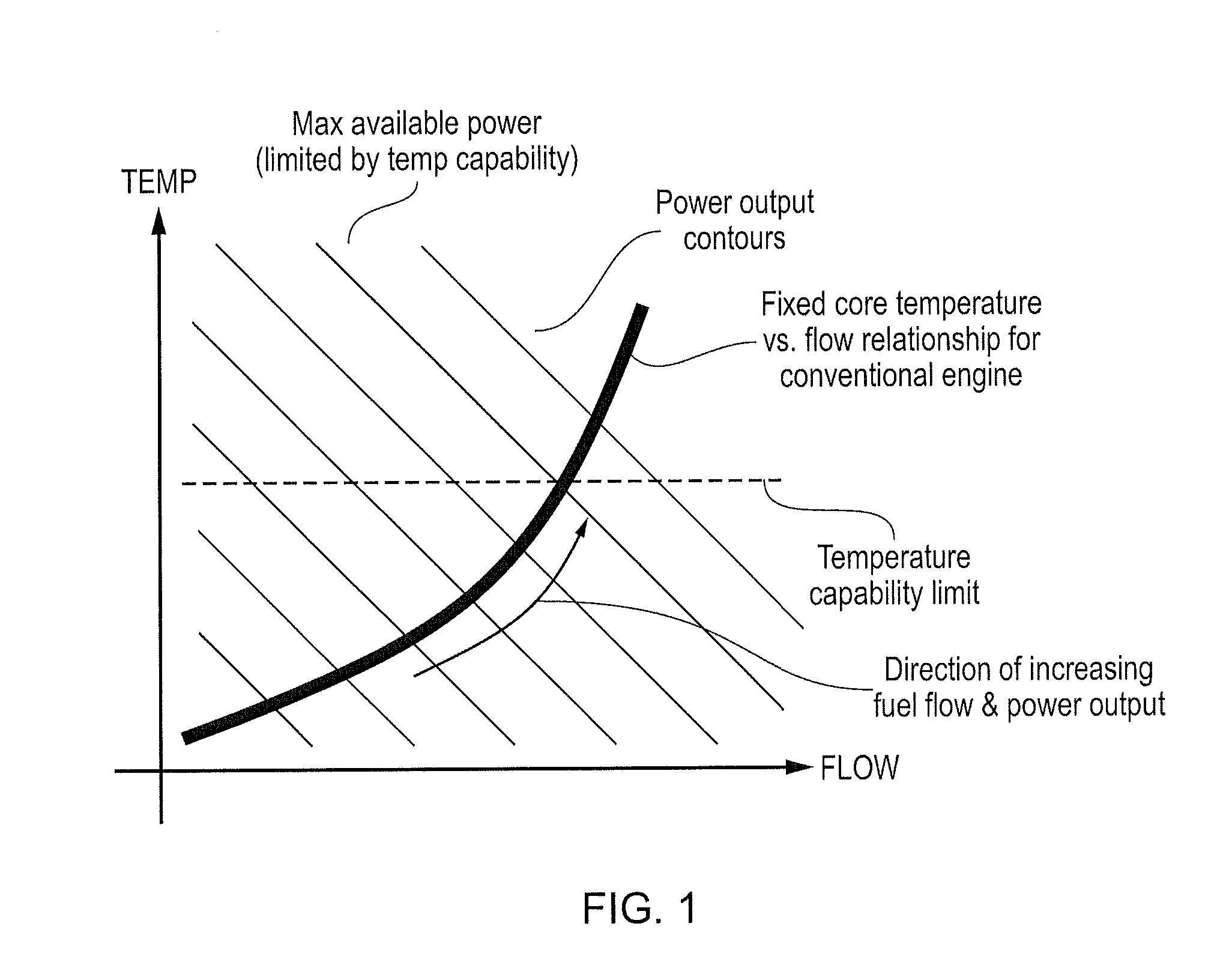
a gas turbine engine and control technology, applied in the direction of machines/engines, efficient propulsion technologies, mechanical apparatuses, etc., can solve the problems of reducing the maximum power output capability of the engine, increasing the operating temperature, and placing a practical limit on the power output availabl

Active Publication Date: 2015-10-29
ROLLS ROYCE PLC
View PDF6 Cites 20 Cited by
  • Summary
  • Abstract
  • Description
  • Claims
  • Application Information

AI Technical Summary

Benefits of technology

[0008]It would be desirable to be able to vary the core flow vs. temperatu...

Problems solved by technology

For an engine of fixed physical size and pressure ratio (and hence core flow) the temperature capability of the engine therefore places a practical limit on the power output available from it.
Firstly, the engine must be physically sized and the temperature capability of the components designed for the most arduo...

Method used


Image

  • Control of a gas turbine engine
  • Control of a gas turbine engine
  • Control of a gas turbine engine

Examples


Embodiment Construction

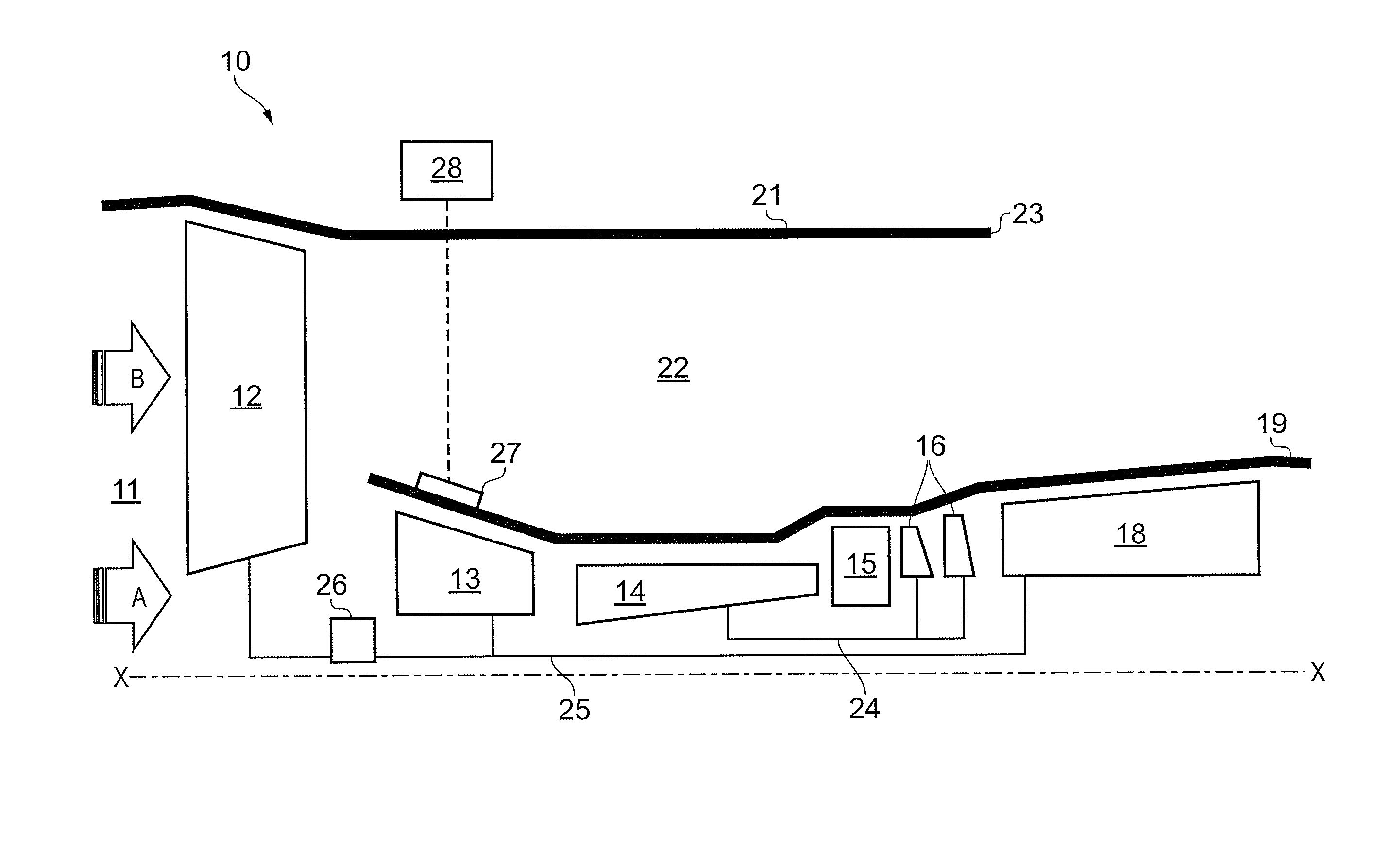
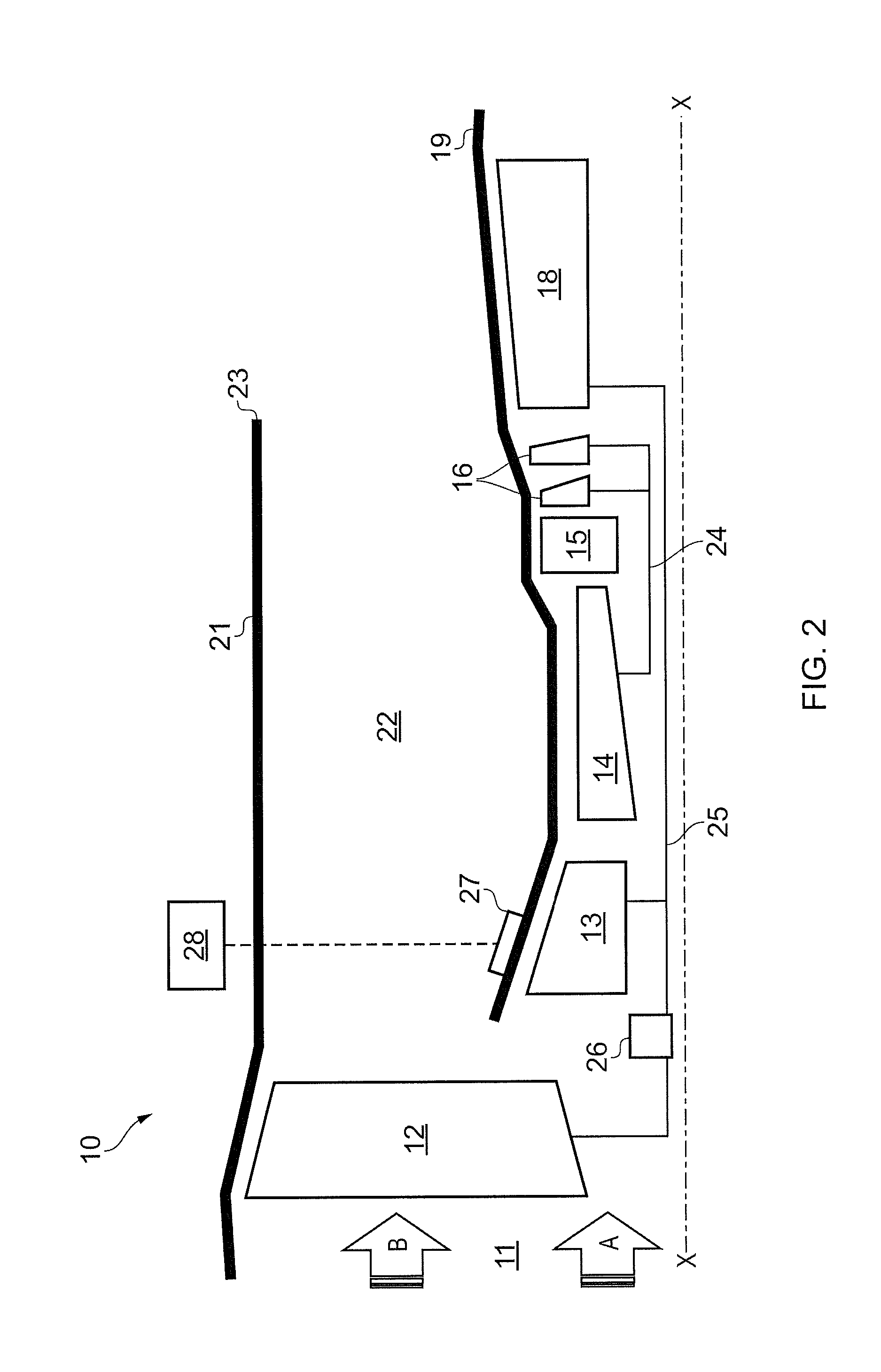
[0049]With reference to FIG. 2, a geared, ducted fan gas turbine engine incorporating the invention is generally indicated at 10 and has a principal and rotational axis X-X. The engine comprises, in axial flow series, an air intake 11, a propulsive fan 12, a booster compressor 13, a core compressor 14, combustion equipment 15, a core turbine 16, a low-pressure turbine 18 and a core engine exhaust nozzle 19. A nacelle 21 generally surrounds the engine 10 and defines the intake 11, a bypass duct 22 and a bypass exhaust nozzle 23.

[0050]During operation, air entering the intake 11 is accelerated by the fan 12 to produce two air flows: a first air flow A into the booster compressor 13 and a second air flow B which passes through the bypass duct 22 to provide propulsive thrust. The booster compressor 13 compresses the air flow A directed into it before delivering that air to the core compressor 14 where further compression takes place.

[0051]The compressed air exhausted from the core compr...


PUM


Abstract

An engine that has, in axial flow series, booster compressor, core compressor, combustion equipment, core turbine, and low-pressure turbine. Core turbine drives core compressor via an interconnecting high-pressure shaft. Low-pressure turbine drives booster compressor via an interconnecting low-pressure shaft. Low-pressure turbine also drives external load having a defined speed characteristic that dictates speed of the low-pressure turbine and booster compressor. Booster compressor has one or more rows of variable stator vanes. The method includes: scheduling variation in the angle of variable stator vanes as a function of speed of the booster compressor wherein the vanes open as booster compressor speed increases; measuring or setting one or more operational parameters which are determinative of temperature at entry to core turbine; and biasing scheduling of angle variation of variable stator vanes as a function of operational parameter(s) to reduce variation in temperature at entry to core turbine.

Description

FIELD OF THE INVENTION[0001]The present invention relates to control of a gas turbine engine.BACKGROUND OF THE INVENTION[0002]The power output from a gas turbine engine is directly proportional to both the temperature at which it operates and the quantity of air that flows through it. For a conventional gas turbine engine in which each compressor is powered by an independent turbine, the relationship between core flow and temperatures is fixed. In order to increase the power output from the engine more fuel must be burned in the combustor. This increases both core flow and temperatures. The operating temperatures of the engine must be closely monitored and the fuel supply regulated to prevent the temperature capability of the engine being exceeded. For an engine of fixed physical size and pressure ratio (and hence core flow) the temperature capability of the engine therefore places a practical limit on the power output available from it.[0003]This is illustrated in FIG. 1 which show...

Claims


Application Information

Patent Timeline
IPC IPC(8): F02C9/22F02C7/36F02C6/00
CPCF02C9/22F02C6/00F02C7/36F05D2270/303F05D2270/05F05D2270/304F05D2220/32F01D17/162F02C9/20F02C9/54F05D2220/76F05D2270/06Y02T50/60
Inventor GARDNER, ALASDAIRROWE, ARTHUR LAURENCETAYLOR, MARK DAVIDHOWARTH, NICHOLAS
Owner ROLLS ROYCE PLC
Why Eureka
Try Eureka