
Enclosed flare stack and method of flaring waste gas

a technology of waste gas and stack, which is applied in the direction of combustion types, lighting and heating apparatus, incinerator apparatus, etc., can solve the problems of a taller external radiation fence, the loss of the ability to direct air flow at a given velocity, and the major cost of enclosed flares

Inactive Publication Date: 2015-10-29
HONEYWELL INT INC
View PDF3 Cites 0 Cited by
  • Summary
  • Abstract
  • Description
  • Claims
  • Application Information

AI Technical Summary

Benefits of technology

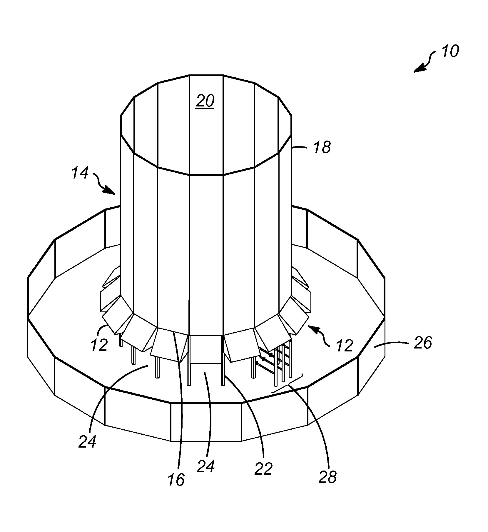
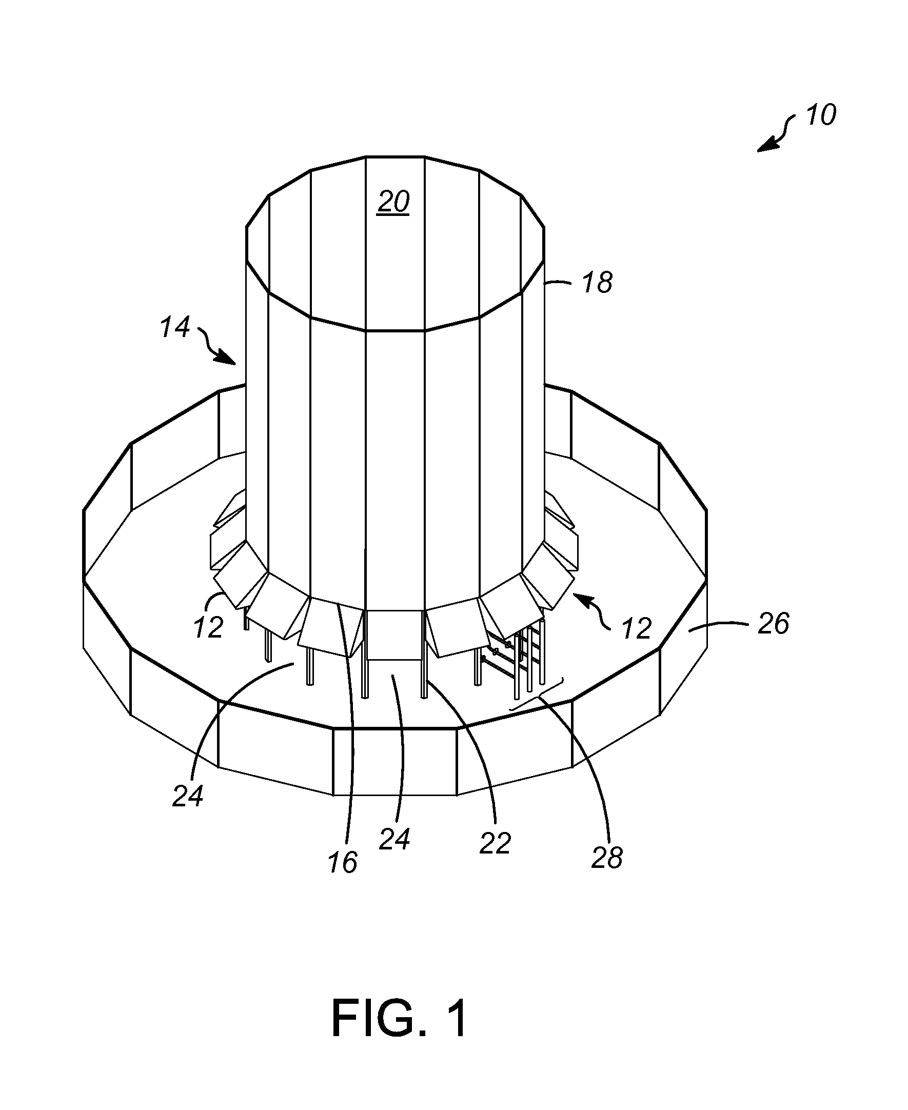
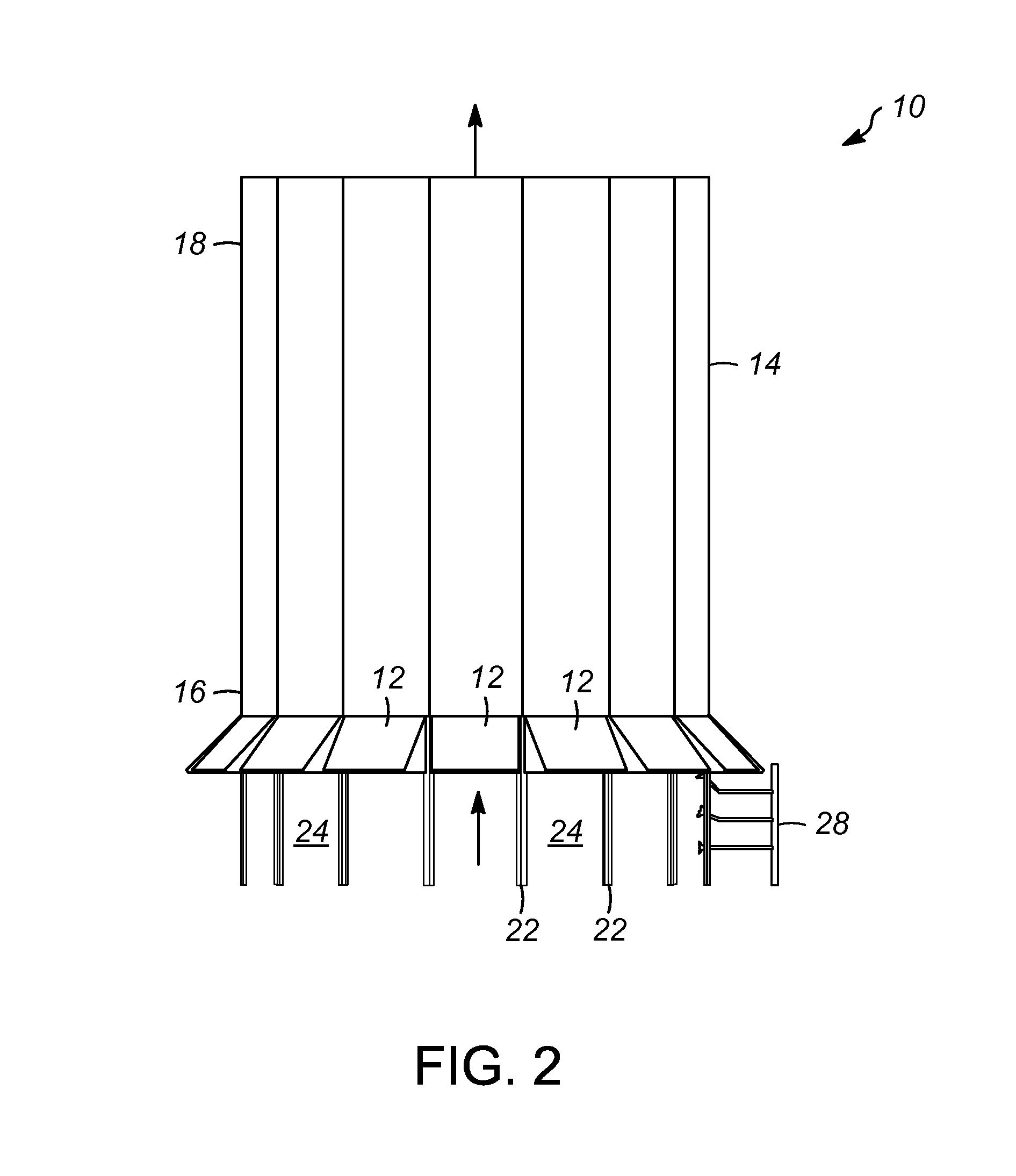
The invention is about an enclosed flare stack that can be used to flare waste gas. The stack has an enclosure assembly with a bottom and an upper portion through which the flared gas escapes. It also has an expanded air entry with an upper panel at a predetermined angle to the upper portion of the enclosure assembly. The expanded air entry has several options for its angle, including a concave angle, a smooth radius downwardly sloping angle, or a combination of these. The expanded air entry can be a plurality of entries. The method of using the enclosed flare stack involves flowing the waste gas through the stack, entraining air through flare windows, and entraining additional air through the expanded air entry with the upper panel at the predetermined angle. The technical benefits of this invention are an improved flaring efficiency, reduced air pollution, and increased safety during the flaring process.

Problems solved by technology

One of the major costs of enclosed flares is the stack enclosure.
A shorter stack enclosure is less expensive, but entrains less air, whereas an enclosure with larger air entries, or “windows” can induce more air through static draft for a given height, but in turn loses the ability to direct the air flow at a given velocity magnitude and also requires a taller external radiation fence, both of which are undesirable.

Method used


Image

  • Enclosed flare stack and method of flaring waste gas
  • Enclosed flare stack and method of flaring waste gas
  • Enclosed flare stack and method of flaring waste gas

Examples


specific embodiments

[0038]While the following is described in conjunction with specific embodiments, it will be understood that this description is intended to illustrate and not limit the scope of the preceding description and the appended claims.

[0039]A first embodiment of the invention is an enclosed flare stack having a flow path for flaring waste gas, the stack comprising an enclosure assembly having a bottom portion with at least one expanded air entry and an upper portion through which the flared waste gas escapes, the expanded air entry comprising at least one upper panel having a predetermined angle with respect to the upper portion of the enclosure assembly; and a flare window adjacent to the expanded air entry of the enclosure assembly. An embodiment of the invention is one, any or all of prior embodiments in this paragraph up through the first embodiment in this paragraph further comprising a radiation fence that completely surrounds and circumnavigates the flare stack. An embodiment of the...


PUM


Abstract

An enclosed flare stack having expanded air entries for flaring waste gas. The flare stack includes an enclosure assembly having a bottom portion with expanded air entries and an upper portion through which the flared waste gas escapes. The enlarged air entries at the bottom end of the stack to reduce entry pressure loss and to increase entrained air flow when flaring waste gas. The enclosed flare stack and method of flaring waste gas also greatly reduce the height of the stack enclosure without greatly increasing the size of the flare windows.

Description

CROSS-REFERENCE TO RELATED APPLICATION[0001]This application claims priority from Provisional Application No. 61 / 983,561 filed Apr. 24, 2014, the contents of which are hereby incorporated by referenceBACKGROUND OF THE INVENTION[0002]This invention relates generally to an enclosed flare stack and method of flaring waste gas, and more particularly to an enclosed flare stack having a series of enlarged air entries at a bottom end of the stack to reduce entry pressure loss and to increase entrained air flow when flaring waste gas.[0003]Flare systems are used in various industries to provide safe disposal of flammable liquids or gases. Flare systems are combustion mechanisms to burn off flammable liquids or gases. By way of example, flare systems may be used in industrial plants to burn off flammable gases released by pressure relief valves. Various types of flares exist, including elevated flares and flares that operate near grade. Near-grade level flares are often called ground flares....

Claims


Application Information

Patent Timeline
IPC IPC(8): F23G7/08
CPCF23G2900/00F23G7/085E04H12/28F23C7/00
Inventor MARTIN, MATTHEW A.
Owner HONEYWELL INT INC
Learn More