Holder and deployment system for surgical heart valves

a deployment system and heart valve technology, applied in the field of prosthetic heart valves, can solve the problems of requiring a large amount of time, and unable to survive the surgical procedure or die, so as to achieve quick and easy replacement of heart valves, reduce time, and reduce the effect of tim

Active Publication Date: 2015-11-05
EDWARDS LIFESCIENCES CORP
View PDF1 Cites 11 Cited by
  • Summary
  • Abstract
  • Description
  • Claims
  • Application Information

AI Technical Summary

Benefits of technology

[0009]The present application discloses prosthetic valves and methods of use for replacing a defective native valve in a human heart. Certain embodiments are particularly well adapted for use in a surgical procedure for quickly and easily replacing a heart valve while minimizing time using extracorporeal circulation (e.g., bypass pump). In particular, the application discloses an advantageous system and method for holding and delivering a hybrid prosthetic heart in less time than previously was possible.
[0011]In a first embodiment, the valve holder connects by a first suture to the prosthetic heart valve, wherein the first suture extends around the second end of the anchoring stent and is placed under tension to constrict the second end to a second peripheral size smaller than the first peripheral size. The first suture desirably passes over a single cutting well on the valve holder such that severing the first suture at the single cutting well releases the tension therein and permits the second end of the anchoring stent to expand toward its first peripheral size.
[0017]severing the first suture at the cutting well to release the tension therein and permit the inflow end of the anchoring stent to expand toward its relaxed size.

Problems solved by technology

Because of the trauma associated with the procedure and the attendant duration of extracorporeal blood circulation, some patients do not survive the surgical procedure or die shortly thereafter.
Due to these risks, a substantial number of patients with defective valves are deemed inoperable because their condition is too frail to withstand the procedure.
Percutaneous and minimally-invasive surgical approaches, some of which avoid cardiopulmonary bypass altogether in “beating heart” procedures, are garnering intense attention.
One hurdle to the acceptance of remote implantation is resistance from doctors who are anxious about converting from an effective, if imperfect, regimen to a novel approach that promises great outcomes but is relatively foreign.

Method used


Image

  • Holder and deployment system for surgical heart valves
  • Holder and deployment system for surgical heart valves
  • Holder and deployment system for surgical heart valves

Examples


Embodiment Construction

[0045]The present disclosure provides a valve holder for hybrid prosthetic heart valves delivered by open-heart surgery, but which include features that decrease the duration of the treatment procedure. The prosthetic heart valves of the present invention are primarily intended to be delivered and implanted using surgical techniques, including the aforementioned open-heart surgery. There are a number of approaches in such surgeries, all of which result in the formation of a direct access pathway to the particular heart valve annulus. For clarification, a direct access pathway is one that permits direct (e.g., naked eye) visualization of the heart valve annulus.

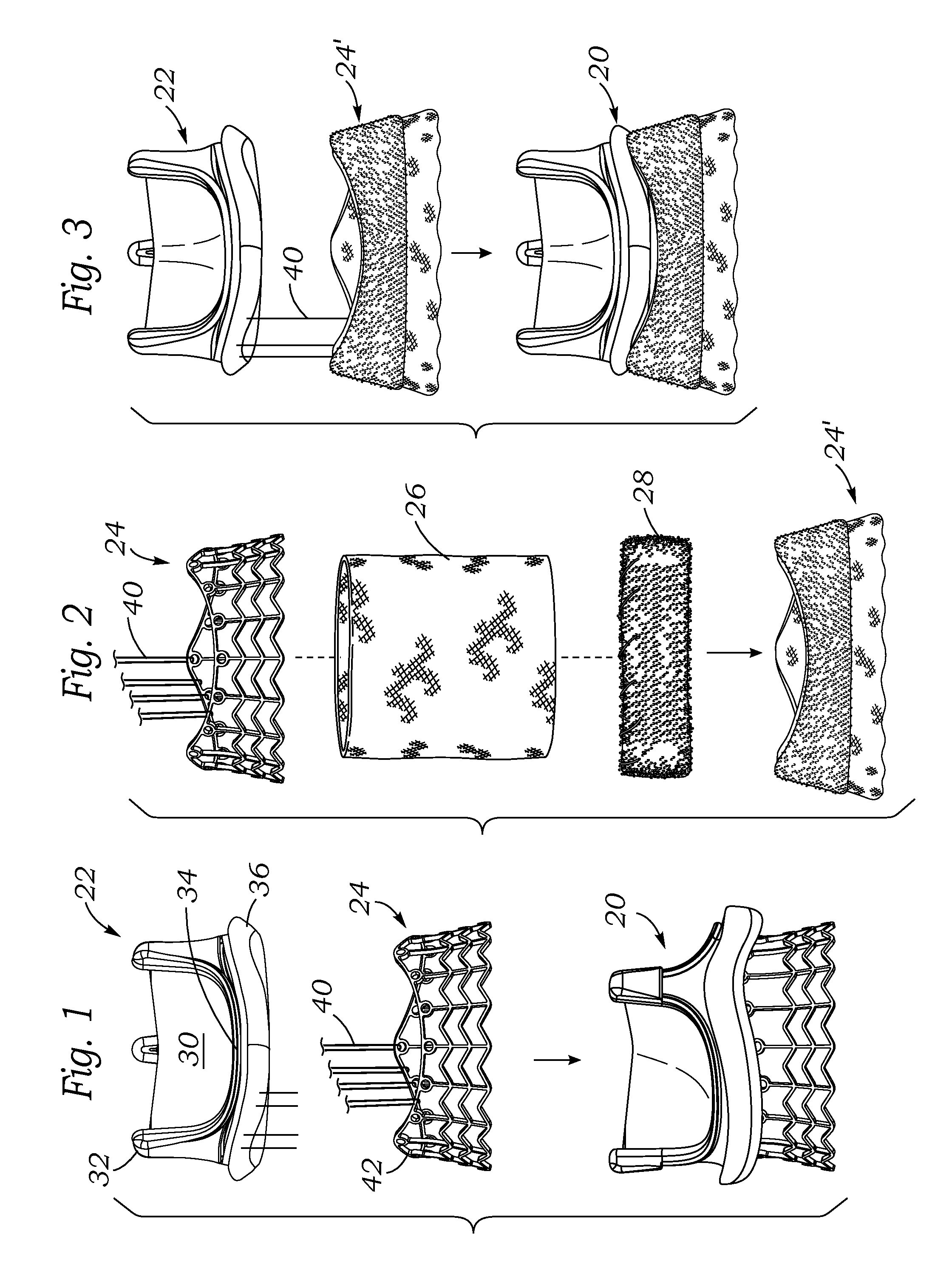
[0046]The “hybrid” prosthetic heart valve has both non-expandable and expandable portions; specifically, an expandable anchoring stent or stent coupled to a non-expandable valve member. With this type of valve, the duration of the anchoring operation is greatly reduced as compared with a typical sewing procedure utilizing an a...


PUM


Abstract

A holder for a hybrid heart valve prosthesis that can be quickly and easily implanted during a surgical procedure is provided. The hybrid heart valve includes a non-expandable, non-compressible prosthetic valve and a self-expandable anchoring stent, thereby enabling attachment to the annulus without sutures. A first suture connects the holder to the valve and constricts an inflow end of the anchoring stent. A second suture connects the holder to the valve and extends down three holder legs to loop through fabric on the valve. Both sutures may loop over a single cutting well on the holder so that severing the first and second sutures at the single cutting well simultaneously releases the tension in the first suture, permitting the inflow end of the anchoring stent to expand, and disconnects the valve holder from the prosthetic heart valve.

Description

CROSS-REFERENCE TO RELATED APPLICATIONS[0001]This application claims the benefit of U.S. Patent Application No. 61 / 986,761, filed Apr. 30, 2014, the entire disclosure of which is incorporated by reference.TECHNICAL FIELD[0002]The present application generally relates to prosthetic valves for implantation in body channels. More particularly, the present application relates to a holder for a hybrid surgical prosthetic heart valve having a non-collapsible / non-expandable valve portion and a self-expanding anchoring stent.BACKGROUND[0003]In vertebrate animals, the heart is a hollow muscular organ having four pumping chambers—the left and right atria and the left and right ventricles—each provided with its own one-way valve to ensure that blood does not flow in the wrong direction. The mitral valve is between the left atrium and the left ventricle, the tricuspid valve between the right atrium and the right ventricle, the pulmonary valve is at the opening of the pulmonary artery, and the a...

Claims


Application Information

Patent Timeline
Patent Type & Authority Applications(United States)
IPC IPC(8): A61F2/24
CPCA61F2230/0069A61F2/2427A61F2/2439A61F2220/0075A61F2/2418A61F2/243A61F2210/00A61F2210/0014
Inventor CHANG, DA-YUFANN, HILDA Z.
Owner EDWARDS LIFESCIENCES CORP
Why Eureka
Try Eureka