
Continuous extrusion device based on twin screw extruder

a technology of extruder and extruder, which is applied in the direction of mixing, transportation and packaging, rotary stirring mixer, etc., can solve the problems of inability to obtain the functions of the degassing device, the pressure inside the degassing device is accurately detected, and the machine is stopped. , to achieve the effect of easy replacement, accurate detection of pressure inside the degassing device, and convenient operation

Inactive Publication Date: 2015-11-05
JAPAN STEEL WORKS LTD
View PDF6 Cites 7 Cited by
  • Summary
  • Abstract
  • Description
  • Claims
  • Application Information

AI Technical Summary

Benefits of technology

This invention is a device that removes inert gas and air from plastic raw materials. It also removes volatile components that can affect the quality of the plastic. The invention allows for the replacement of filters without stopping the operation of the extruder, so a continuous extrusion operation can be achieved. Additionally, the device cools the filters to prevent the plastic material from melting.

Problems solved by technology

A conventional extrusion device has problems such as the following, due to having the configuration described above.
More specifically, the degassing device used in Patent Document 1 above removes inert gas components or incorporated air that has become mixed into the plastic raw material, and volatile components remaining in the plastic material, and the like, by using an external suction source, such as a vacuum pump, but if the filter becomes blocked, the machine is stopped and the functions of the degassing device cannot be obtained unless the filter is replaced.
Furthermore, in the extrusion device of Patent Document 2, supposing that the filter (porous wall section) becomes blocked by bulk material in the form of dust, a method is adopted to carry out pressurized gas purging in order to maintain the degassing function, but when the pressurized gas purging is carried out, the degassing function is lost, a large amount of gas is included in bulk material in the form of powder, the apparent bulk density falls, whereby the amount of material processed may decline.

Method used


Image

  • Continuous extrusion device based on twin screw extruder
  • Continuous extrusion device based on twin screw extruder
  • Continuous extrusion device based on twin screw extruder

Examples


Embodiment Construction

[0028]It is an object of the present invention to provide a continuous extrusion device based on a twin screw extruder whereby continuous operation can be performed by operating a twin screw extruder using one filter, of a pair of filters, while the other filter of the pair is being replaced.

Practical Examples

[0029]A preferred embodiment of a continuous extrusion device based on a twin screw extruder according to the present invention is described below with reference to the drawings.

[0030]Parts which are the same as or equivalent to the prior art example are labelled with the same reference numerals.

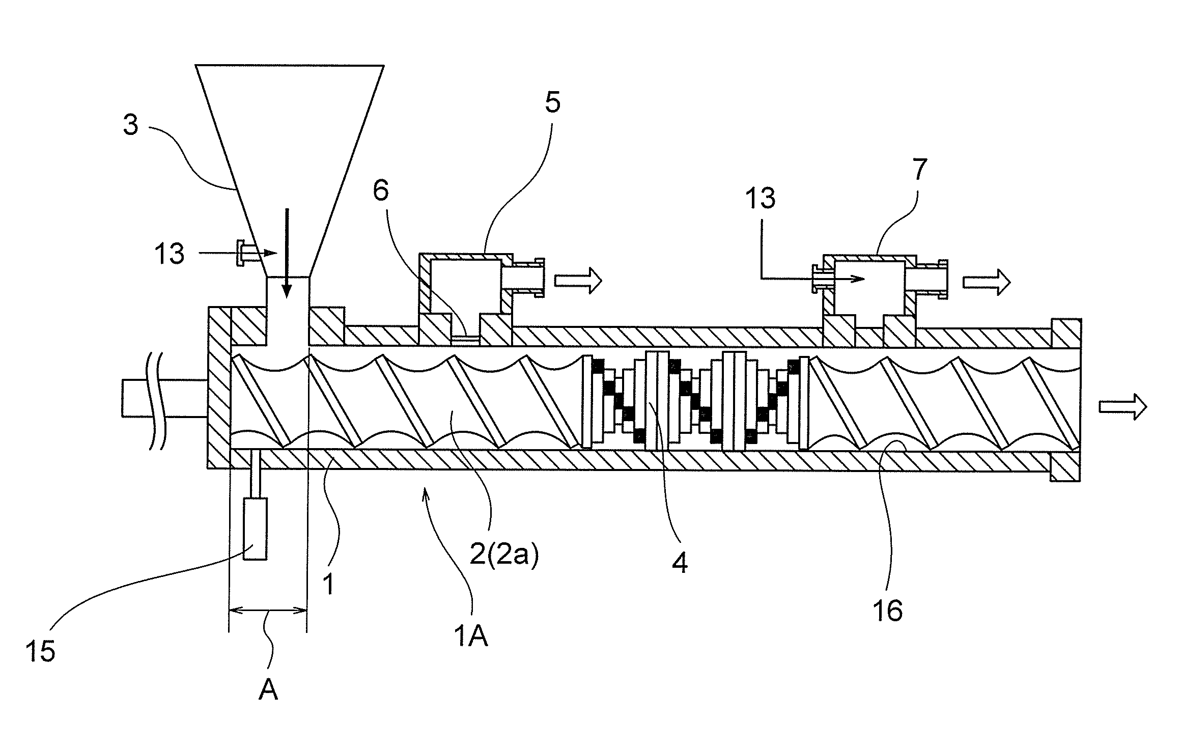
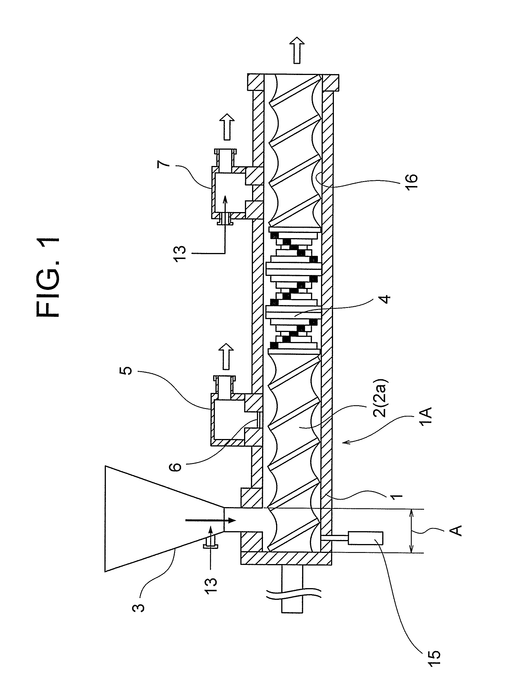
[0031]In FIG. 1, reference numeral 1 is a cylinder, 2, 2a are screws, 3 is a hopper, 4 is a mixing section, 5 is a degassing device, 6 is a filter, and 7 is a downstream-side vent; inert gas 13 is supplied to the hopper 3 and the vent 7 in order to prevent oxidation of the plastic, but there may be a case where the inert gas supply is not implemented.

[0032]A first pressure detector 15 f...


PUM

PropertyMeasurementUnit
Pressureaaaaaaaaaa
Shapeaaaaaaaaaa

Abstract

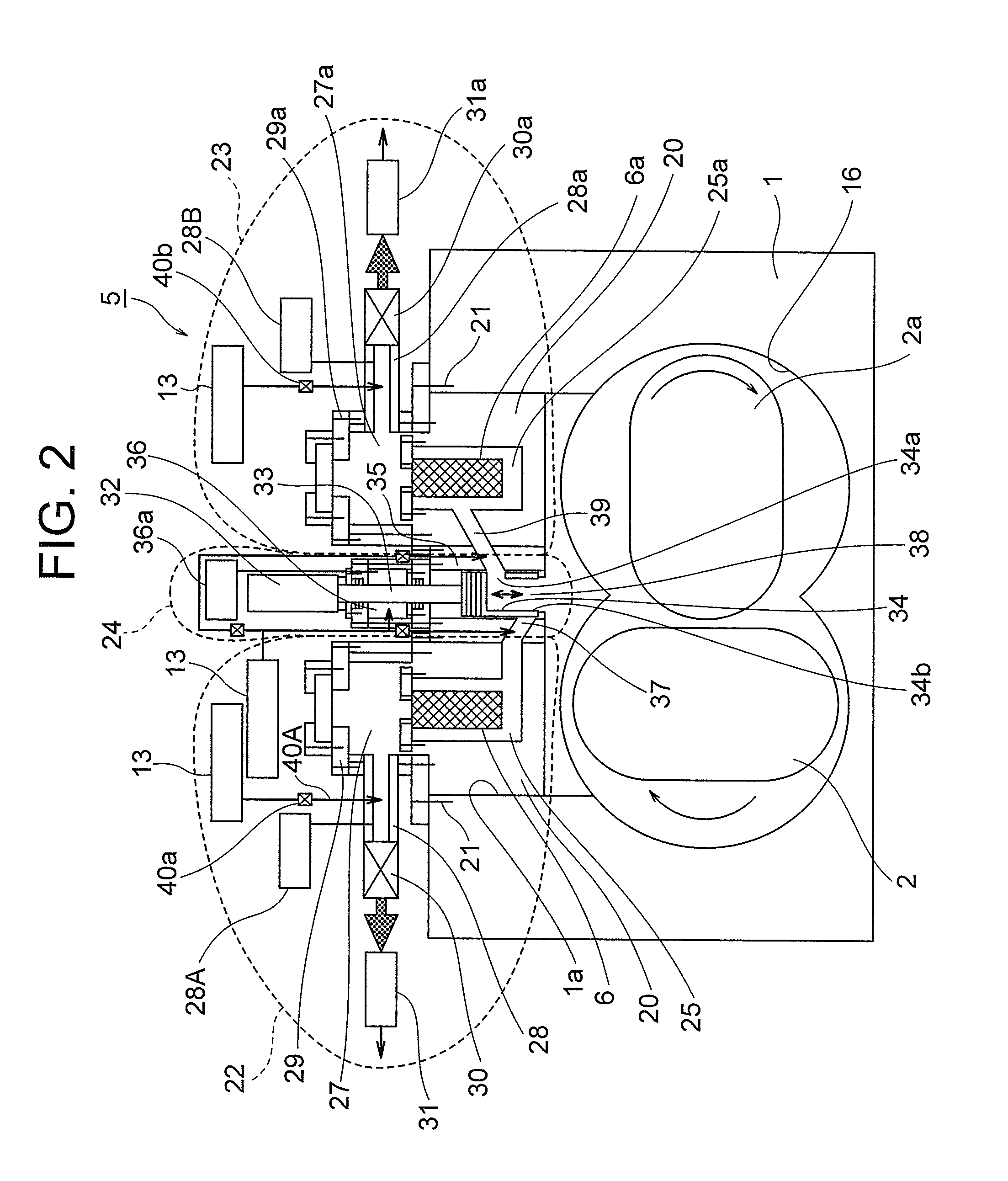
The present invention performs, by using a pair of filters, continuous operation of a twin screw extruder even during replacement of a filter. The continuous extrusion device based on a twin screw extruder of the present invention has a pair of filters (6, 6a) provided in a degassing device (5), and a partition valve (24) having a valve (34) for setting the filters (6, 6a) and a screw hole (16) of a cylinder (1) to a communicating or non-communicating state, degassing being performed by using the second filter (6a) during replacement of the first filter (6), and the twin screw extruder being operated continuously even during replacement of the filters (6, 6a).

Description

TECHNICAL FIELD[0001]The present invention relates to a continuous extrusion device based on a twin screw extruder, and in particular, to novel improvements for enabling continuous operation of a twin screw extruder by operating the extruder using one of a pair of filters during replacement of the other one of the filters.BACKGROUND ART[0002]Conventionally, an extrusion device based on a twin axis extruder of this type has been proposed in Patent Document 1, and the configuration of this device is shown in FIG. 5. FIG. 5 uses an equivalent diagram rather than the same diagram as Patent Document 1. In FIG. 5, 1 is a cylinder, 2 is a screw, 3 is a hopper, 4 is a mixing section, 5 is a degassing device, 6 is a filter, and 7 is a downstream vent. An inert gas 13 may be supplied to the hopper 3 and the vent 7 in order to prevent oxidation of the plastic. The vent 7 may be open to the atmosphere or may be depressurized by a vacuum pump, or the like, and the vent 7 may also be omitted.[000...

Claims


Application Information

Patent Timeline
IPC IPC(8): B29C47/76B29C47/92B01F15/02B29C47/68B01F7/00B01F15/06B29C47/40B29B7/80B29C48/295B29C48/40B29C48/54B29C48/57B29C48/69B29C48/76B29C48/92
CPCB29C47/763B29C47/402B29C47/767B29C47/92B29B7/801B29C47/68B01F2215/0049B01F15/06B01F15/0292B29C2947/92019B29C2947/92561B29C2947/924B01F2015/061B01F7/00883B29B7/82B29B7/845B29C2791/006B29C48/145B29C48/295B29C48/54B29C48/57B29B7/483B29B7/488B29C48/763B29C48/92B29C48/402B29C48/767B29C2948/924B29C2948/92019B29C2948/92561B29C48/40B29C48/69B01F27/42B01F35/90B01F35/7547B01F2035/98B01F2101/2805
Inventor TAKAMOTO, SEIJIISHIKAWA, MAKOTOKAKIZAKI, JUNFUJITA, REOYATA, KYOHEI
Owner JAPAN STEEL WORKS LTD
Learn More