Method for stabilizing a two wheeled vehicle

a two-wheeled vehicle and vehicle stabilization technology, applied in the direction of process and machine control, cycle equipment, instruments, etc., can solve the problems of rear wheel skidding, two-wheeled vehicle greatly oversteer, inability to drive in stable conditions, etc., to achieve the effect of improving the safety of travel

Active Publication Date: 2015-11-05
ROBERT BOSCH GMBH
View PDF6 Cites 28 Cited by
  • Summary
  • Abstract
  • Description
  • Claims
  • Application Information

AI Technical Summary

Benefits of technology

[0010]In the method according to the present invention, the boundary value is determined as a function of at least one further, current vehicle state variable. Consequently, the boundary value is not a fixed, constant value, but is rather established as a function of the driving situation. This has the advantage that, based on the better adaptation to the current driving state, a precise, sensitive regulation is possible, and with that, a better stabilization of the two-wheeled vehicle. As the vehicle state variable, which goes into the determination of the boundary value, the current two-wheeled vehicle speed, for example, comes into consideration, which is available as a measured value. It is also possible, however, to take into account other vehicle state variables in the determination of the boundary value, as long as the vehicle state variables represent a driving dynamics value of the two-wheeled vehicle. For example, a transverse dynamic state variable, such as the vehicle's transverse acceleration or the yaw rate may be taken into account.
[0012]According to a further expedient embodiment, the boundary value is updated continuously as a function of the vehicle state variable. As soon as the control variable, that is, the attitude angle or a value correlated with is, has reached the vehicle state-dependent boundary value, the stabilizing regulation begins. As of this time, the boundary value may furthermore be updated continuously, in that the current vehicle state variable is measured or ascertained from measured values, and the boundary value is calculated as a function of this current value. This has the advantage that the boundary value, which represents the control threshold, is continuously updated or corrected, the control threshold being lowered with increasing stabilization.

Problems solved by technology

Critical driving stets may occur if the current driving speed, the steering angle and / or the sloping position of the two-wheeled vehicle are not adapted to the radius of the curve and the road conditions and weather conditions.
At excessive curve speed, too great a change in speed caused by an acceleration or braking in a sloping position and at changes in the coefficient of friction between the tires and the road, unstable driving situations may occur at which the two-wheeled vehicle greatly oversteers and the rear wheel skids in the direction of the outside of the curve.

Method used


Image

  • Method for stabilizing a two wheeled vehicle
  • Method for stabilizing a two wheeled vehicle

Examples


Embodiment Construction

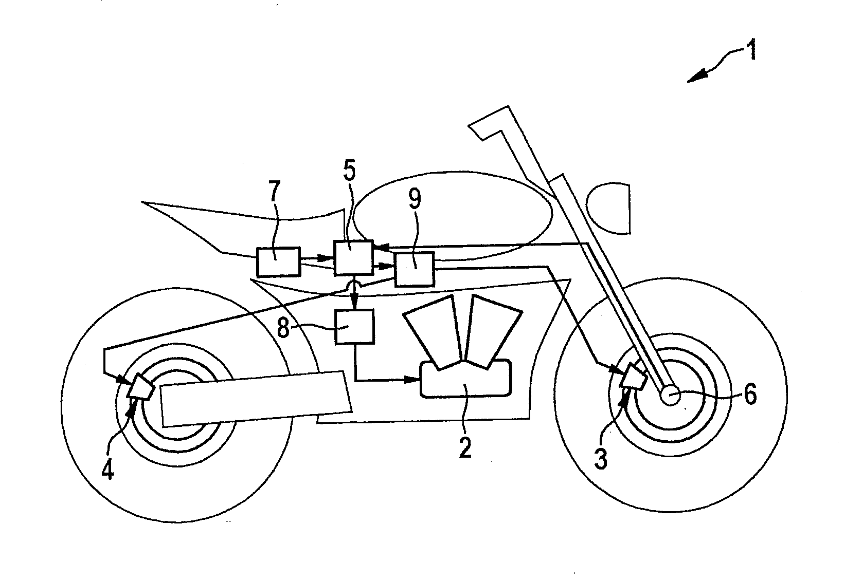
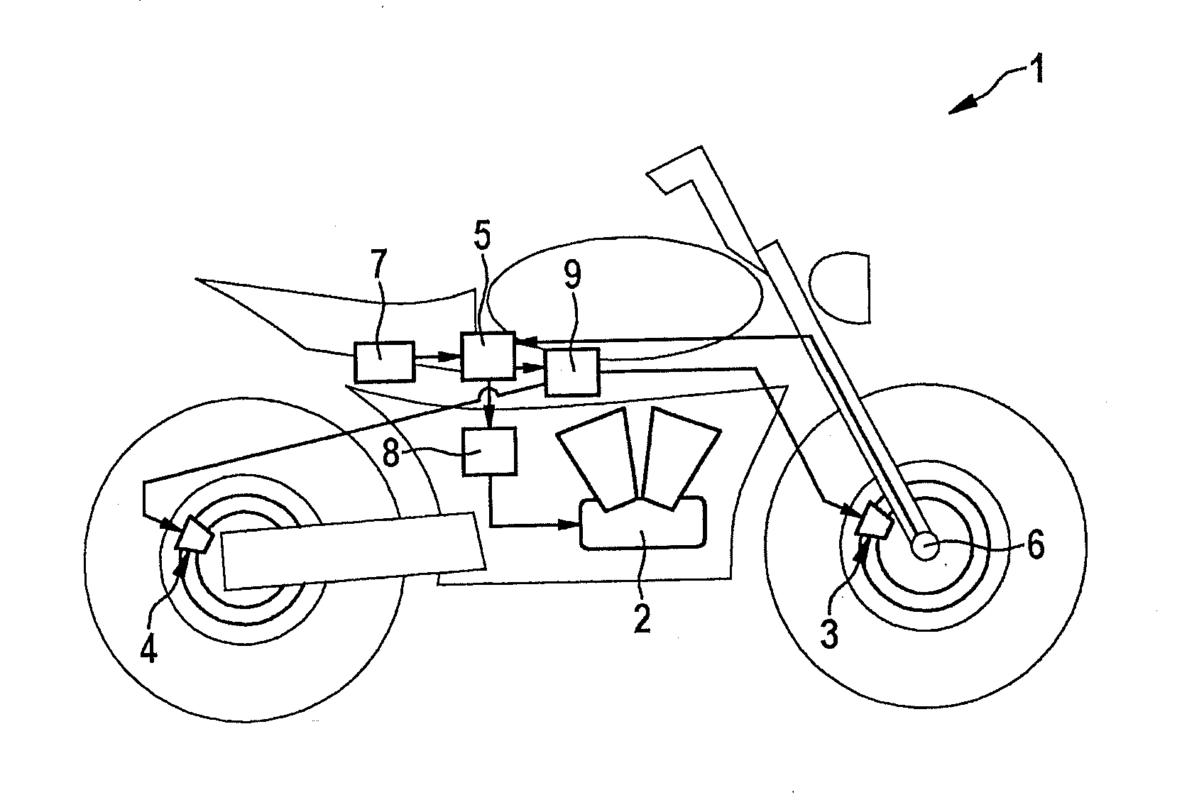
[0019]In the FIGURE, a motorcycle 1 is shown having a drive engine 2 executed as an internal combustion engine. In addition, front wheel brake 3 and rear wheel brake 4 are drawn in schematically. Motorcycle 1 is equipped with a regulating or control unit 5, and furthermore, a wheel rotational speed sensor 6 is situated on the front wheel which, the same as inertial sensor 7, is a component of the sensor system on the motorcycle. The vehicle's longitudinal acceleration and the transverse acceleration are able to be determined via inertial sensor system 7, and, in addition, also expediently the yaw rate and the rolling rate. Motorcycle 1 is furthermore equipped with an engine control unit 8, via which the engine drive torque may be set, and with and antilock (ABS) control unit 9 for actuating front wheel brake 3 and, if necessary, also rear wheel brake 4. Regulating or control unit 5 communicates with the sensor system as well as with engine control unit 8 and ABS control unit 9.

[0020...


PUM


Abstract

In a method for stabilizing a two-wheeled vehicle, the current attitude angle is compared to an associated boundary value which is determined as a function of at least one current driving state variable.

Description

FIELD OF THE INVENTION[0001]The present invention relates to a method for stabilizing a two-wheeled vehicle.BACKGROUND INFORMATION[0002]In order to be able to ride a motorcycle through a curve, in a stable manner, the speed, the sloping position and the steering angle have to be adapted to the current curve radius as well as the road and weather conditions, otherwise there is the danger that the motorcycle oversteers, and the rear wheel skids away laterally in the curve. If the motorcycle in this situation then gets onto a roadway section having a higher coefficient of friction, there is the danger of a rollover in the direction of the outside of the curve, which goes hand-in-hand with the danger of a considerable injury.[0003]German document DE 10 2010 003 951 A1 proposes, as a stabilization measure, carrying out a driving dynamics regulation in a motorcycle when the attitude angle or the attitude angle change exceeds a specified threshold value. The attitude angle is determined ba...

Claims


Application Information

Patent Timeline
Patent Type & Authority Applications(United States)
IPC IPC(8): B60W30/02B60W10/04B60W10/184G05D1/08
CPCB60W30/02G05D1/0891B60W10/04B60W10/184B60W2520/28B60W2720/18B60W2520/14B60W2520/105B60W2520/125B60W2720/14B60W2720/16B60W2520/26B60T8/261B60W10/06B60W10/18B60W30/146B60W2300/36B60W2520/20B62J27/00B62M7/02B60T2230/02B60Y2200/12B62K11/00B62J45/4151
Inventor KLEWS, MATTHIASLEMEJDA, MARKUS
Owner ROBERT BOSCH GMBH
Why Eureka
Try Eureka