Method for controlling a dual-supercharged combustion engine

a technology of supercharged combustion engines and combustion engine control, which is applied in the direction of electric control, machines/engines, mechanical equipment, etc., can solve the problems of complex system to achieve and control, and does not take into account the physical behavior of gas flows

Inactive Publication Date: 2015-11-05
INST FR DU PETROLE
View PDF10 Cites 16 Cited by
  • Summary
  • Abstract
  • Description
  • Claims
  • Application Information

AI Technical Summary

Problems solved by technology

The engine described in this document comprises an additional controllable valve between the turbocharger and the mechanical compressor, which makes the system more complex to achieve and to control (the number of actuators to be controlled is larger).
In addition, the control method described in this document does not take account of the physical behavior of the gas flows at the intake.

Method used


Image

  • Method for controlling a dual-supercharged combustion engine
  • Method for controlling a dual-supercharged combustion engine
  • Method for controlling a dual-supercharged combustion engine

Examples


application examples

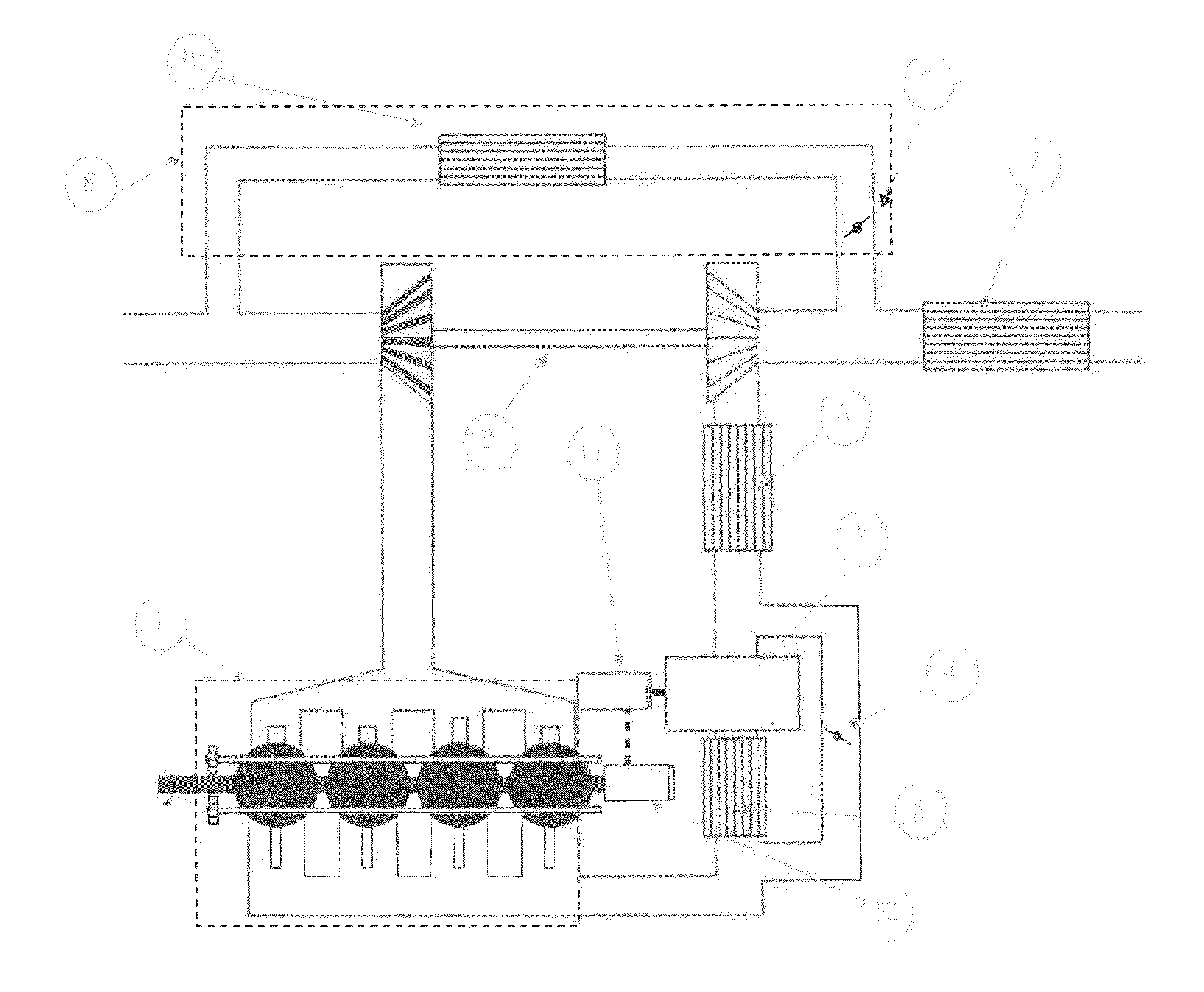
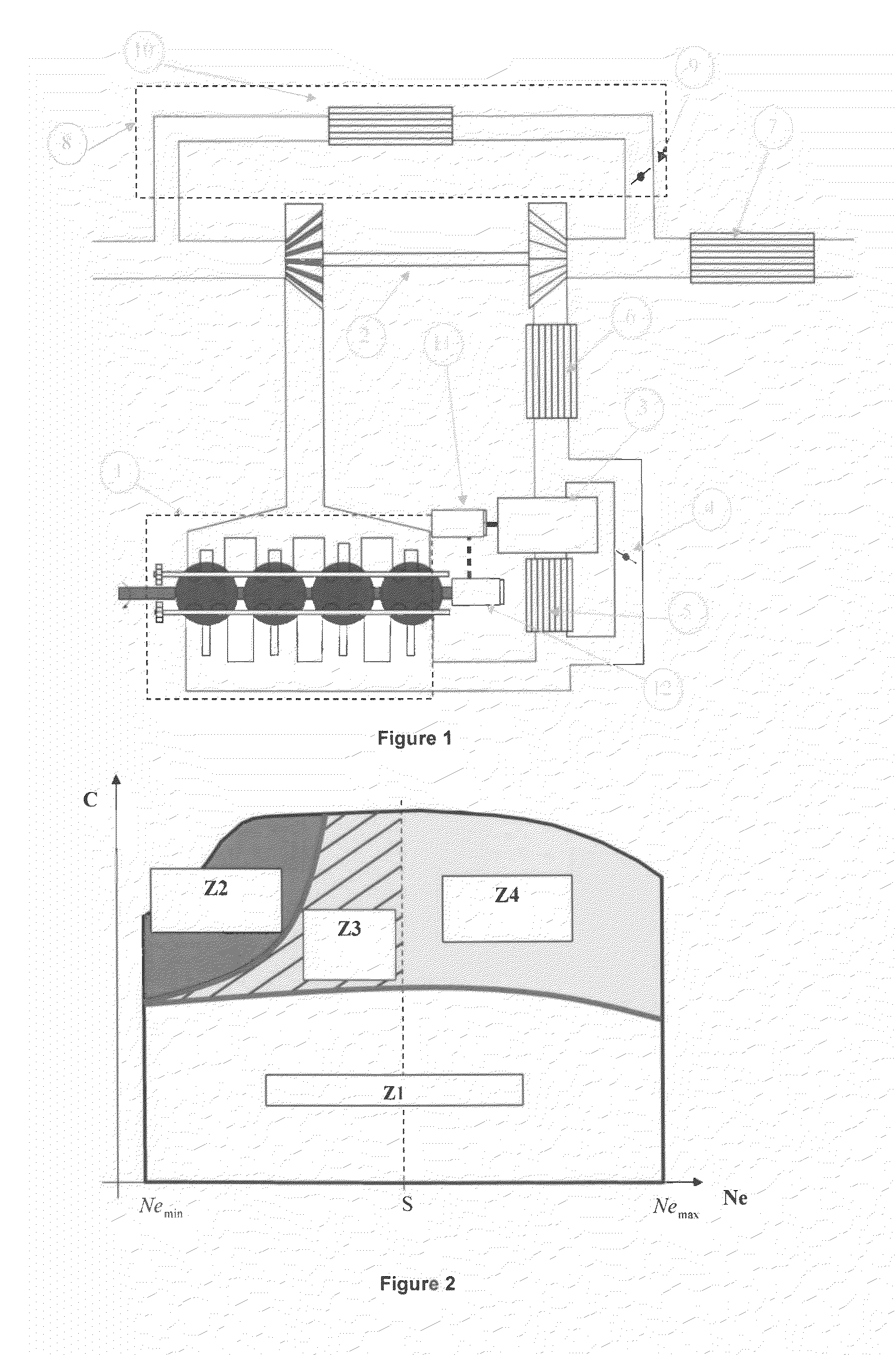
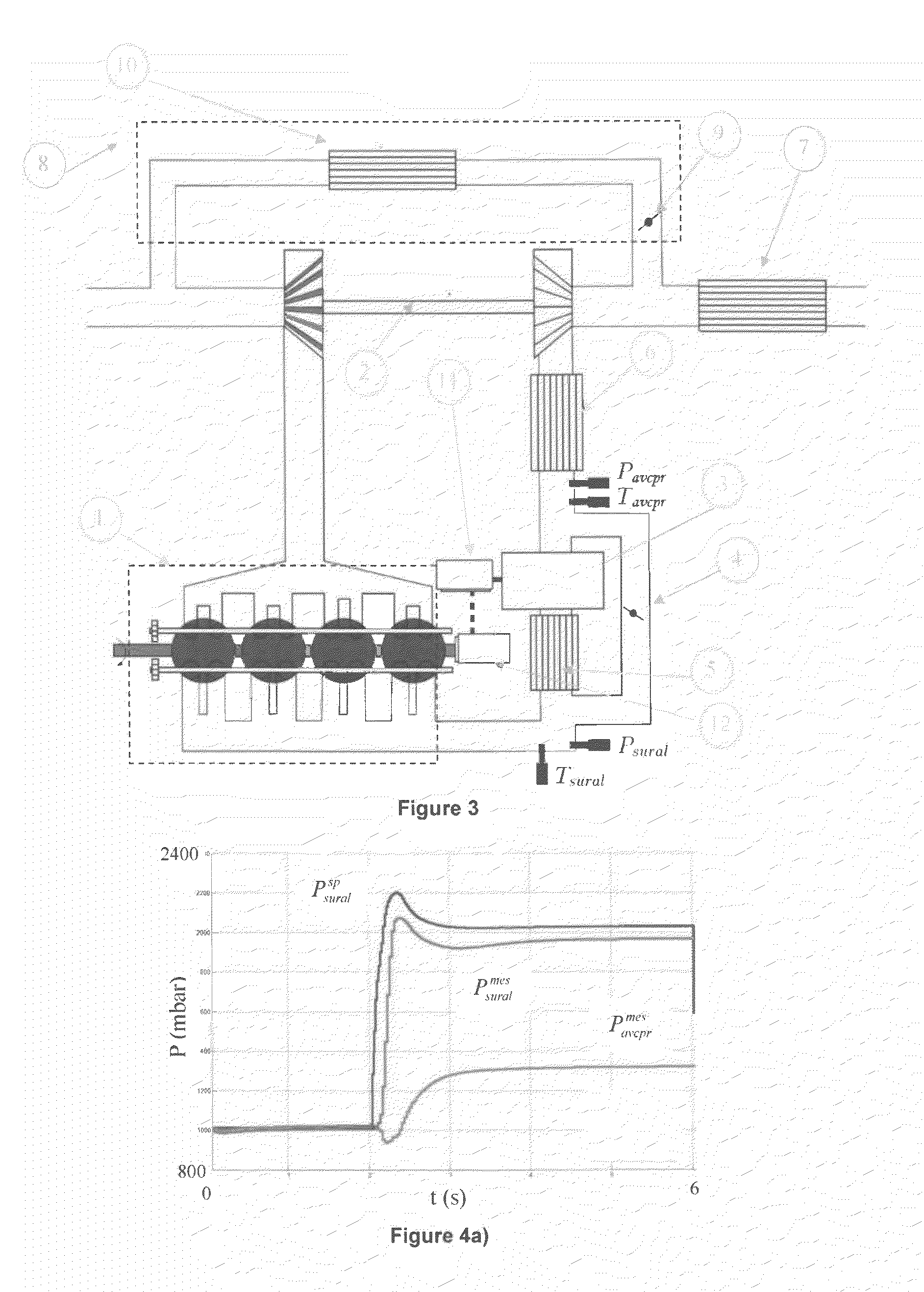
[0106]In order to check the behavior of the combustion engine with the method according to the invention, simulations were performed with the open-loop control and the closed-loop control for the combustion engine instrumented according to FIG. 3. For these simulations, the predetermined threshold S of use of the mechanical compressor is set at 3000 rpm. FIGS. 4 to 6 correspond to the open-loop control as described in stage 4) and FIGS. 7 and 8 correspond to the closed-loop control as described in the variant embodiments paragraph.

[0107]FIGS. 4a) to 4d) illustrate charging at an engine speed of 1000 rpm (zone Z2 in FIG. 2). FIG. 4a) shows the setpoint Psuralsp and measured Psuralmes boost pressure, as well as the pressure measured upstream from the positive-displacement compressor Pavcprmes. FIG. 4b) shows the setpoint and the measured value of positive-displacement compressor speed Ncpr. FIGS. 4c) and 4d) show the openings of the air actuators, of the by-pass valve and of the VGT (...


PUM


Abstract

The invention relates to a combustion engine equipped with a dual supercharging system in which a mechanical compressor is driven by an electric motor. The method controls a combustion engine with the electric motor being controlled by determining a rotational speed setpoint for positive-displacement compressor using a supercharge volume filling model.

Description

CROSS REFERENCE TO RELATED APPLICATIONS[0001]Reference is made to PCT Patent Application No. PCT / FR2013 / 052515, filed on Oct. 21, 2013, and French Patent Application No. 12 / 03.260, filed on Nov. 30, 2012, which applications are incorporated herein by reference in their entirety.FIELD OF THE INVENTION[0002]The present invention relates to the field of combustion engine control, and in particular to dual-supercharged combustion engines.DESCRIPTION OF THE PRIOR ART[0003]What is referred to as engine supercharging increases the amount of fuel / air mixture within the engine cylinders in relation to standard operation. Supercharging and a fortiori dual supercharging allows increasing the efficiency of a combustion engine without modifying the rotational speed thereof. Indeed, the engine torque (and therefore the power) depends on the angle formed between the connecting rod and the crankshaft, on the gas pressure within the cylinder, referred to as Mean Effective Pressure (or MEP), and on t...

Claims


Application Information

Patent Timeline
Patent Type & Authority Applications(United States)
IPC IPC(8): F02B37/04F02B39/04F02B37/16F02B29/04F02D23/00F02M25/07
CPCF02B37/04F02D23/00F02B39/04F02B37/16F02B29/04F02M25/07F02B29/0412F02B29/0418F02B37/24F02B39/10F02D29/06F02D41/0007F02D2200/0402F02D2200/0406F02D2200/0414F02M26/06F02M26/00Y02T10/12
Inventor THOMAS, LEROYCHASSE, ALEXANDRECHAUVIN, JONATHAN
Owner INST FR DU PETROLE
Why Eureka
Try Eureka