Method and system for controlling a flying wing

a flying wing and control system technology, applied in the direction of machine/engine, process and machine control, instruments, etc., can solve the problems of limited robustness of the flying wing, low reliability, high cost, etc., to improve energy generation, improve the reliability, and remove the feedback of the sensor

Active Publication Date: 2015-11-05
MINESTO
View PDF0 Cites 7 Cited by
  • Summary
  • Abstract
  • Description
  • Claims
  • Application Information

AI Technical Summary

Benefits of technology

[0011]One object of the invention is to remove as many unnecessary parts and sensors as possible while still being able to maintain control of the flying wing, thus providing a more robust flying wing. A further object is to remove sensor noise feedback into the rudder servo by not using sensor input in model feedback phase for controlling the flying wing, thereby improving energy generation, decreasing service cost and reducing the risk of catastrophic failure of the flying wing. This is achieved in that the method only uses the above mentioned input values thereby reducing the number of sensors needed. Further, by using a model feedback phase the sensor feedback is replaced by model feedback effectively reducing the noise from the remaining sensors as no sensor inputs are fed directly to the control system of the flying wing. The method allows positioning of the flying wing in the optimal horizontal position, aligning the flying wing to the direction of the sea current.
[0012]The method initially uses measured input values for control but after a predetermined distance along the predetermined trajectory has been traversed and when a deviation between a measured value of the vertical position and a modelled value of the vertical position is below a threshold value the method switches to using modelled values for feedback. This reduces the sensor noise that impacts the control surface movements.

Problems solved by technology

All this leads to limited robustness of the flying wing and involves high cost in the form of for instance lower reliability, greater complexity of the flying wing to achieve desired control properties, decreased time before serviceability is exceeded and increased development times.
The sensors used may exhibit a level of noise which when used to control the control surfaces causes mechanical fatigue due to unnecessary movement of the control surfaces.
Traditional solutions such as Kalman filters cannot remove all the noise from sensors.
Sensors may additionally experience wear from being exposed to the fluid stream.

Method used


Image

  • Method and system for controlling a flying wing
  • Method and system for controlling a flying wing
  • Method and system for controlling a flying wing

Examples


Embodiment Construction

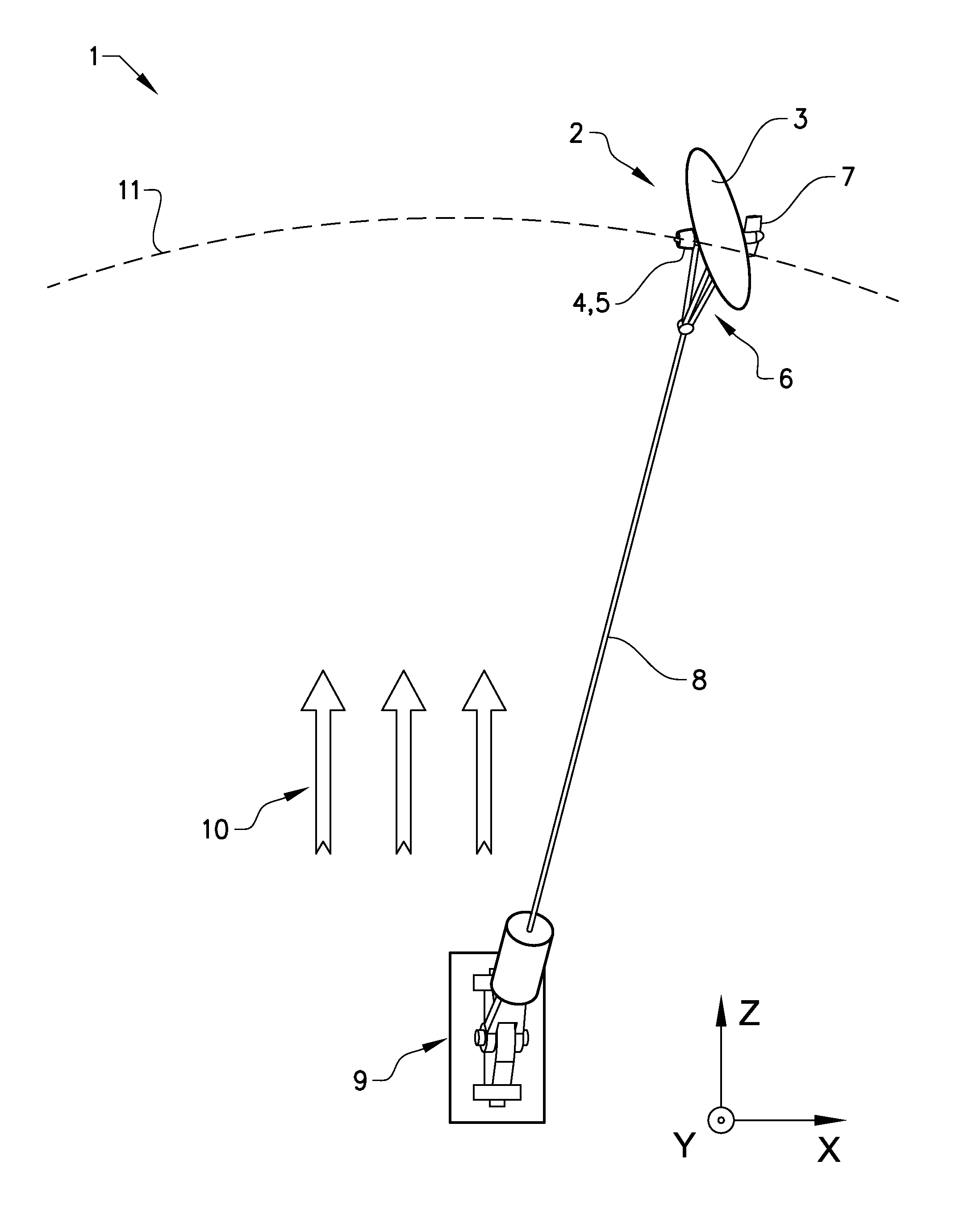
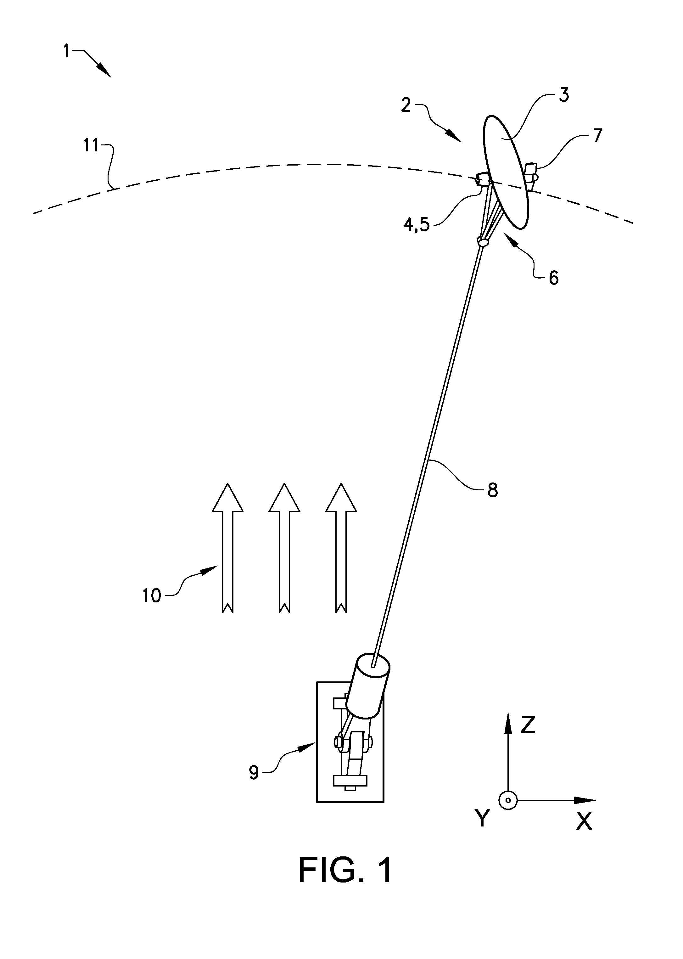
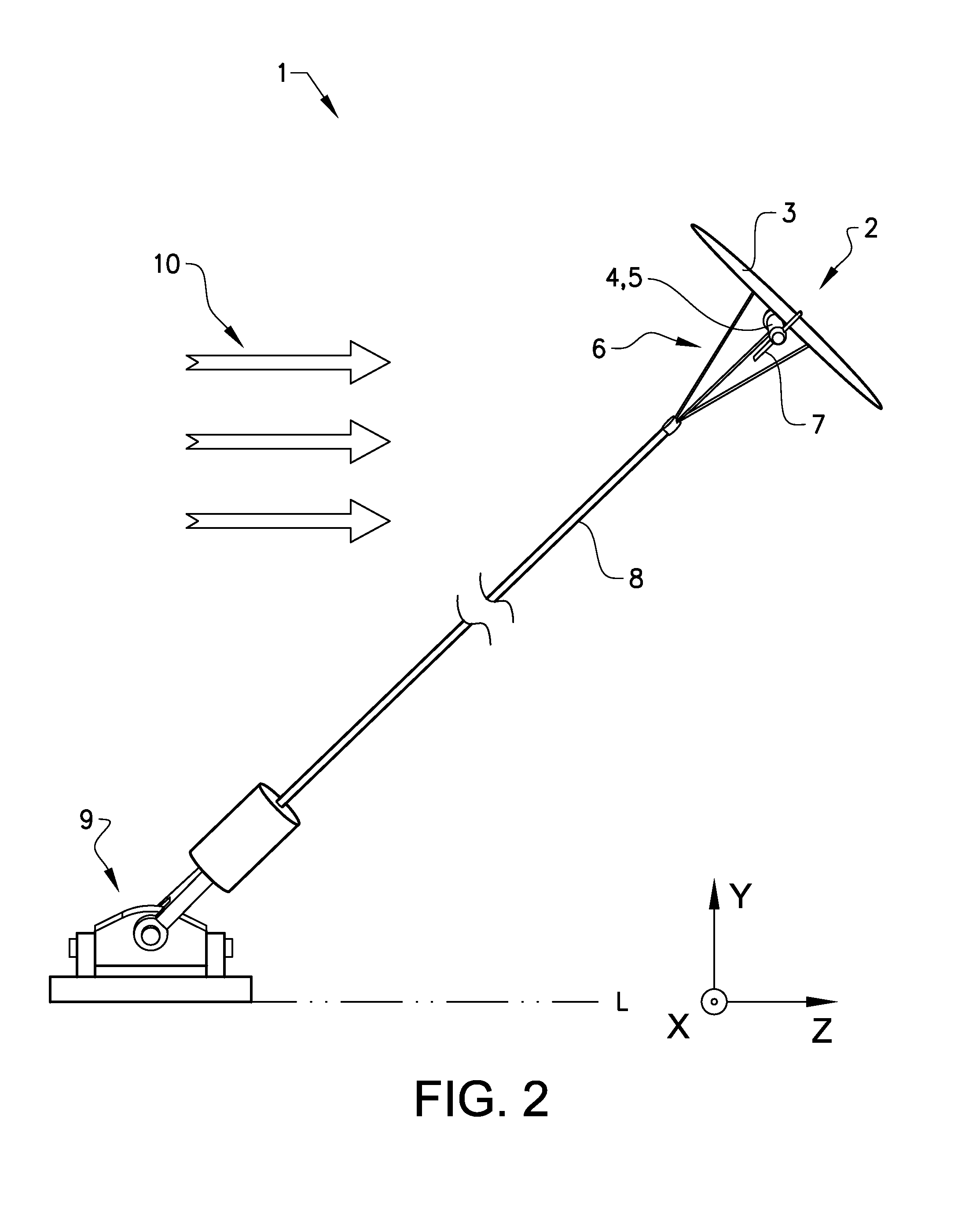
[0054]An overview of a system 1 according to the invention is shown in FIG. 1. The system 1 comprises a flying wing 2 where the flying wing 2 comprises a wing 3, a nacelle 4, a turbine 5 for producing electrical energy, struts 6 and at least one control surface 7. The system 1 further comprises a tether 8 attaching the flying wing 2 to a structure 9. The structure 9 can be positioned on a surface such as any ground surface or the bottom of a sea, lake or the ocean. The structure 9 may also be positioned on the surface of a sea, lake or ocean. The structure 9 is preferably fixed or secure in place. The flying wing system 1 and the method for controlling the flying wing 2 according to the invention can thus be used both on land and submerged under water. The flying wing 2 moves by that a fluid stream 10 moves over the wing 3 and creates lift. The fluid stream 10 can for instance be wind, a tidal stream or an underwater current. By using the control surface 7 the flying wing 2 can be m...


PUM


Abstract

The invention relates to a method for control of a flying wing. The flying wing is arranged to be controlled to move along a predetermined trajectory by means of a fluid stream passing a wing of the flying wing. The flying wing comprises at least one control surface for controlling the movement of the flying wing along the predetermined trajectory. The flying wing is positioned in a reference frame where the x-axis is directed horizontally along a level L above which the flying wing moves, the y-axis is perpendicular to the x-axis in a vertical direction and the z-axis is perpendicular to the x-axis along the level L in a direction along the principal direction of the fluid stream. The invention further relates to a system comprising a flying wing and a computer-readable medium for use with a flying wing.

Description

TECHNICAL FIELD[0001]The invention relates to a method for control of a flying wing. The wing is arranged to be controlled to move along a predetermined trajectory by means of a fluid stream passing the wing. The wing comprises at least one control surface for controlling the movement of the flying wing along the predetermined trajectory. The flying wing is positioned in a reference frame where the x-axis is directed horizontally along a level above which the flying wing moves, the y-axis is perpendicular to the x-axis in a vertical direction and the z-axis is perpendicular to the x-axis along said level in a direction along the principal direction of the fluid stream. The invention further relates to a system comprising a flying wing and a computer-readable medium for use with a flying wing.BACKGROUND ART[0002]Flying wings are known in the art. The control of a flying wing uses a number of control surfaces to control the movement of the flying wing. The control surfaces depend on i...

Claims


Application Information

Patent Timeline
Patent Type & Authority Applications(United States)
IPC IPC(8): G05D1/08F03D9/00B64C39/02G05D1/02
CPCG05D1/0866B64C39/022F03D9/002G05D1/0202F03B17/06F03D5/00F05B2210/16F05B2240/917F05B2240/97F03D5/005Y02E10/70Y02E10/728F03D9/25Y02E10/30Y02E10/72F05B2240/9174F03D9/30F03D13/22Y02E10/20
Inventor MOVERT, ANDERSHILLERBORG, PER
Owner MINESTO
Why Eureka
Try Eureka