Multi-operating switch unit for vehicles

a multi-operating, switch technology, applied in the direction of mechanical control devices, instruments, manual control with single control member, etc., can solve the problems of increasing the possibility of erroneous operation of the switch, complicated vehicles, etc., to reduce manufacturing costs, improve design freedom, and minimize problems

Active Publication Date: 2015-11-05
LS AUTOMOTIVE TECH CO LTD
View PDF6 Cites 14 Cited by
  • Summary
  • Abstract
  • Description
  • Claims
  • Application Information

AI Technical Summary

Benefits of technology

[0025]The multi-operating switch device for a vehicle according to the embodiments of the present invention as constructed above have the following advantageous effects.
[0026]The multi-operating switch device is mounted at a steering wheel or a console switch device of the inside of a vehicle so that a combined operation can be implemented to select or control the electrical operation of a navigation device, an audio multimedia device, and an air conditioner of the vehicle, which are used in the inside of the vehicle.
[0027]In addition, the multi-operating switch device for a vehicle of the present invention minimizes the number of constituent elements and concentrates a switch sensor and the like on a single substrate to minimize a problem associated with an electrical wiring and thus improve a degree of freedom of design and assemblability, thereby reducing the manufacturing cost due to improvement of productivity.
[0028]Moreover, the multi-operating switch device for a vehicle of the present invention can minimize a mounting space through a compact configuration or a partition of an arrangement region of various operations, and prevent or minimize the possibility of erroneous operation of the switch due to interference between the constituent elements.
[0029]Fur...

Problems solved by technology

The structure of the vehicular switch becomes more complicated in proportion to an increase in func...

Method used


Image

  • Multi-operating switch unit for vehicles
  • Multi-operating switch unit for vehicles
  • Multi-operating switch unit for vehicles

Examples


Embodiment Construction

[0051]Now, preferred embodiments of the present invention will be described hereinafter in detail with reference to the accompanying drawings. It should be noted that the same elements in the drawings are denoted by the same reference numerals although shown in different figures. In the following description, the detailed description on known function and constructions unnecessarily obscuring the subject matter of the present invention will be avoided hereinafter.

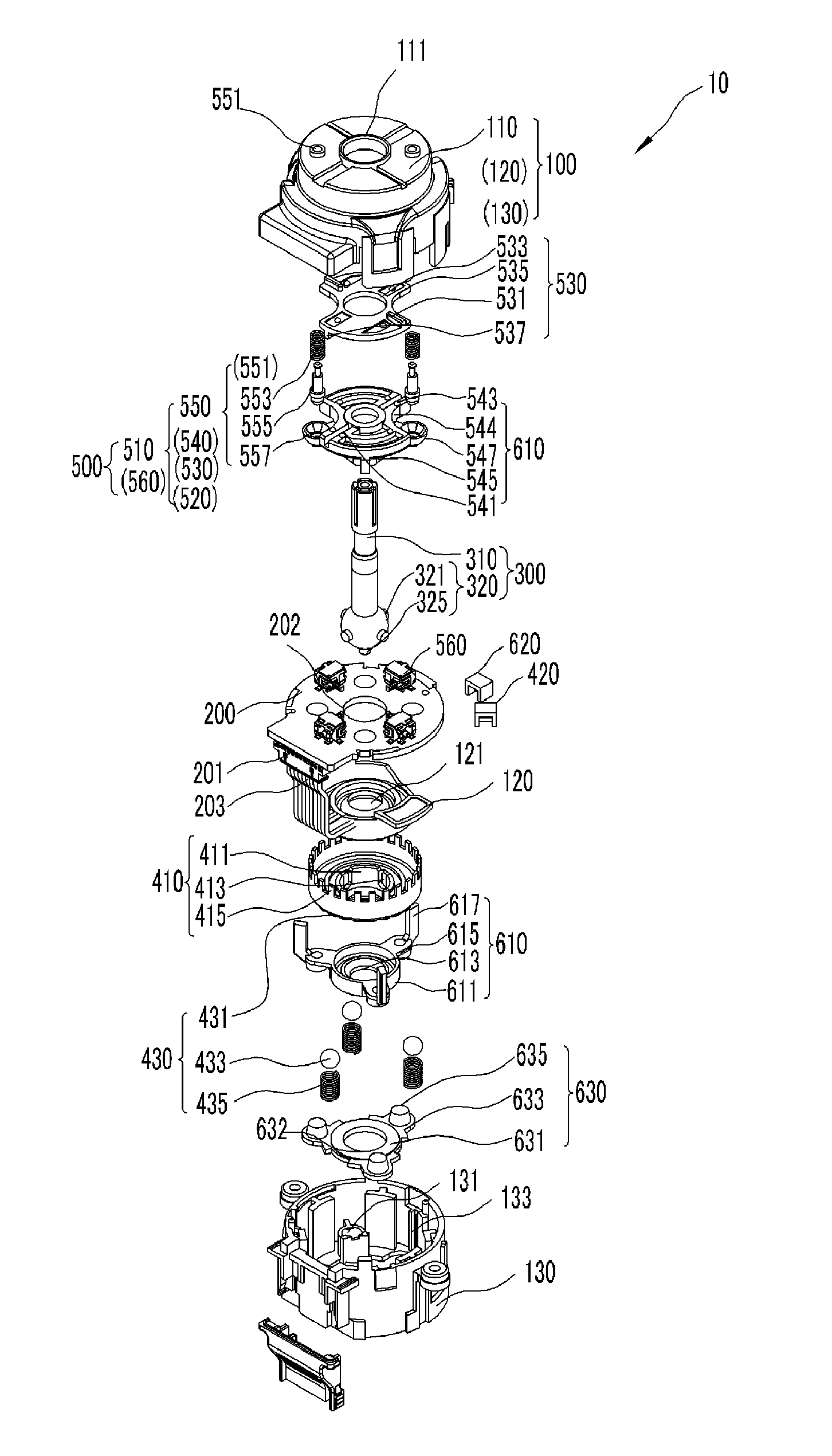
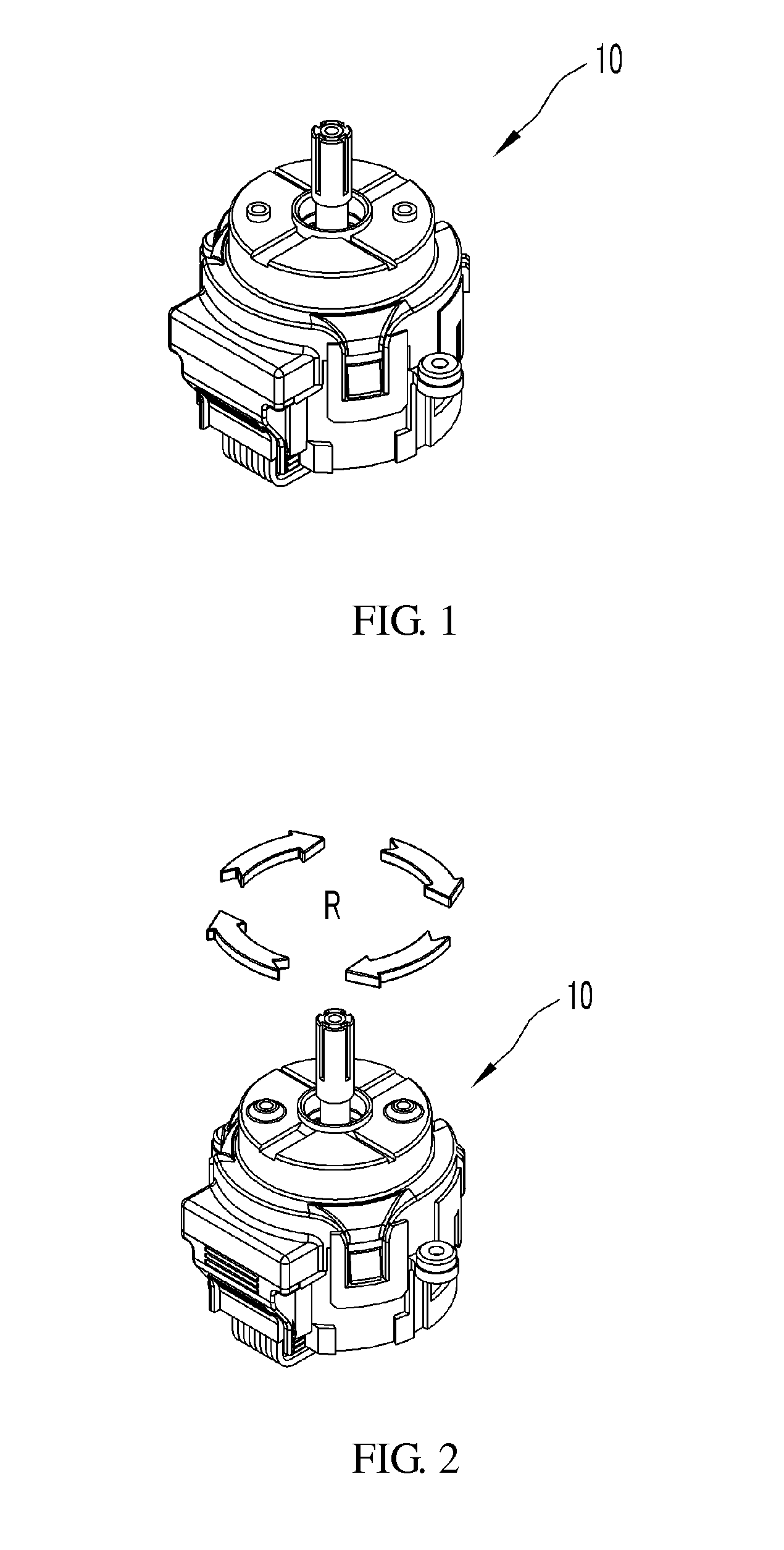
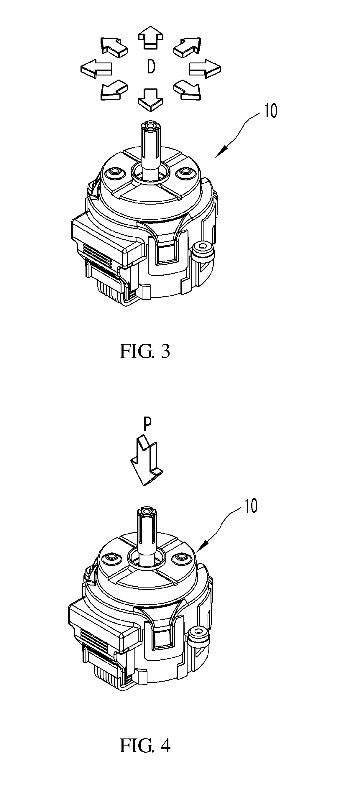
[0052]A multi-operating switch device 10 for a vehicle in accordance with the present invention includes a housing unit 100, a substrate 200, a switch shaft unit 300, a rotary switch unit 400, a directional switch unit 500, and a push switch unit 600. The multi-operating switch device 10 for a vehicle in accordance with the present invention is a switch device that is used in a vehicle. The switch device enables the implementation of various manipulation states thereof so that it is used to control various functions of the ...


PUM


Abstract

Provided is a multi-operating switch unit for vehicles including: a housing part; a substrate; a switch shaft part; a rotary switch part; a directional switch part; and a push switch part. The directional switch part has: a directional slide part in which the position thereof can vary in the housing part due to a tilting directional operation of the switch shaft part; a directional switch that is arranged on the substrate and is operated due to the positional variation of the directional slide part; and a directional return part that returns the directional slide part and the switch shaft part. The directional return part has a return plunger; a return elastic part; and a return groove. The return plunger can be movable in the axial length direction of the switch shaft part with respect to the housing part, and the return groove is formed in the directional slide part.

Description

TECHNICAL FIELD[0001]The present invention relates to a switch installed in a vehicle, and more particularly, to a vehicular switch which implements a combined operation thereof through a simple and compact structure.BACKGROUND ART[0002]In general, a steering wheel assembly for vehicles includes a steering wheel, a steering column, a steering roll connector assembly, and a multi-function switch assembly. The steering wheel is intended to allow a driver to set the steering direction. The rotation of the steering wheel by the driver is transferred to vehicle wheels through the steering column so that the steering angle of the vehicle is set. In addition, a vehicle such as an automobile requires functions of various kinds of convenient means for offering a more stable and comfortable driving state, beyond a function of the vehicle as a means of transportation.[0003]For example, the steering wheel of a vehicle which is recently produced includes a window switch for opening or closing a ...

Claims


Application Information

Patent Timeline
IPC IPC(8): H01H25/06H01H21/04H01H19/04H01H13/50H01H13/04
CPCH01H25/06H01H13/50H01H13/04H01H2235/01H01H21/04H01H2231/026H01H19/04G05G9/047G05G9/04792G05G9/04796H01H25/04G05G2009/04781G05G2009/04777G05G2009/04744H01H19/11H01H2025/046H01H2025/048
Inventor NOH, SAM JONGKIM, JUNG HANYUN, SANG KUKIM, SUNG KYOUNG
Owner LS AUTOMOTIVE TECH CO LTD
Why Eureka
Try Eureka