Image capturing apparatus and imaging method

Active Publication Date: 2015-11-05
CANON KK
View PDF3 Cites 10 Cited by
  • Summary
  • Abstract
  • Description
  • Claims
  • Application Information

AI Technical Summary

Benefits of technology

[0013]As a solution to the above-described issues, the present invention provides a high-precision image capturing apparatus that suppresses noise in an image signal, minimizes reduction in resolution in a longitudinal directio

Problems solved by technology

Thus, this technique poses a challenge in that, since the exposure setting value for controlling the image sensor is determined in accordance with the imaging, this setting value is not suitable for the focus detection, which results in variability in the results of the focus detection.
The configuration described in Japanese Patent Application La

Method used


Image

  • Image capturing apparatus and imaging method
  • Image capturing apparatus and imaging method
  • Image capturing apparatus and imaging method

Examples


Example

First Embodiment

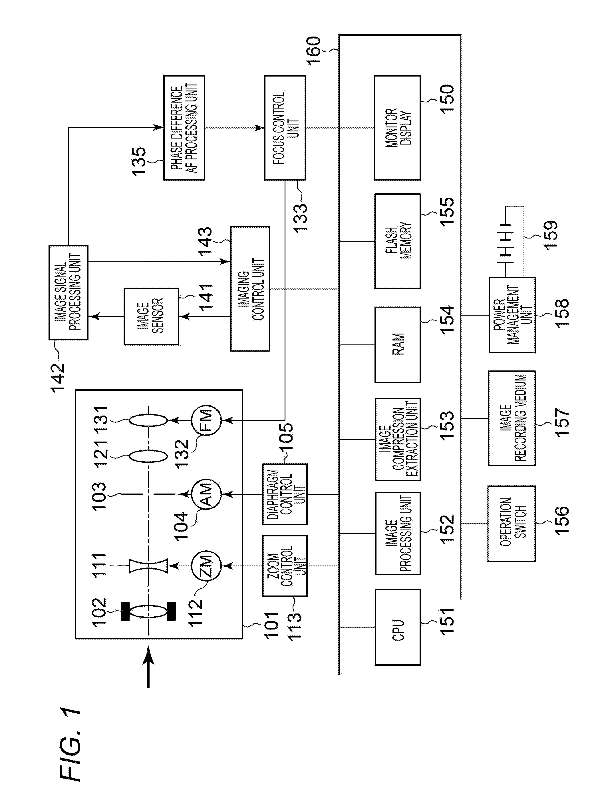
[0030]The configuration of an image capturing apparatus according to the present embodiment will now be described with reference to FIG. 1. FIG. 1 is a block diagram illustrating the configuration of an image capturing apparatus 100.

[0031]The image capturing apparatus 100 may be, but not limited to, a video camera or a digital still camera that captures an image of a subject and has the capability of storing moving image data and / or still image data in various media, such as a tape, a solid-state memory, an optical disk, and a magnetic disk.

[0032]The units included in the image capturing apparatus 100 are connected via a bus 160. These units are controlled by a main CPU 151 (central processing unit).

[0033]The image capturing apparatus 100 employs a focus detection device that performs focus detection of a phase-difference type by using an image sensor including photoelectric conversion elements (a first photoelectric conversion element and a second photoelectric conv...

Example

Second Embodiment

[0156]A method of controlling the ratio of the focus detection pixel line addition to the correlation amount addition in a focus detection region according to a second embodiment of the present invention will now be described. In the first embodiment, the method of comparing contrast as the pixel line addition is performed with one line at a time by using image information from the current frame or the previous frame has been described. In the present embodiment, a method of setting the focus detection pixel line addition count and the correlation amount addition count in a focus detection region on the basis of edge detection and subject contrast will be described.

[0157]Components similar to those in the first embodiment are designated with similar reference signs in this embodiment, and their descriptions are omitted.

[0158]A main CPU 151 functions as a subject recognition unit that detects information on a subject on the basis of an output signal output from an ex...


PUM


Abstract

An image capturing apparatus includes an image sensor having focus detection pixels arrayed in pixel lines, and controls a ratio of pixel line addition to signal correlation amount addition in a focus detection region in accordance with subject information to perform focus detection with increased resolution and suppressed noise based on an image signal of a subject slanting in relation to the focus detection region.

Description

BACKGROUND OF THE INVENTION[0001]1. Field of the Invention[0002]The present invention relates to an image capturing apparatus, such as a digital still camera and a video camera, and in particular relates to an image capturing apparatus having an automatic focus adjusting function of an imaging-plane phase difference type.[0003]2. Description of the Related Art[0004]One type of autofocus (AF) employed for an image capturing apparatus, such as a camera, is phase-difference detection (hereinafter referred to as “phase difference AF”). The phase difference AF technique involves dividing a light beam passing through an exit pupil of the photographic lens into two light beams; these divided light beams are then received by a pair of focus detection sensors.[0005]An amount of difference between signals output in accordance with the amount of received light by each sensor, i.e. the relative positional displacement amount in the dividing direction of the light beams (hereinafter referred to ...

Claims


Application Information

Patent Timeline
IPC IPC(8): H04N5/232H04N5/369G03B13/36
CPCH04N5/23212H04N5/3696G03B13/36G02B7/34H04N23/672H04N25/704H04N23/843H04N25/134
Inventor OHARA, NAOYUKI
Owner CANON KK
Why Eureka
Try Eureka