Swath Roller Attachment for a Swather Tractor

Inactive Publication Date: 2015-11-12
MACDON INDS
View PDF22 Cites 4 Cited by
  • Summary
  • Abstract
  • Description
  • Claims
  • Application Information

AI Technical Summary

Benefits of technology

[0036]Preferably the depending members or cylinders provide a floating action by retracting in response to loads from the swath roller greater

Problems solved by technology

This has advantage that it does not rust and can be manufactured cheaply but it has disadvantages that it slips on the crop and therefore may not properly rotate in a rolling action.
This arrangement manufactured by Free Form Plastics has the disadvantage that the amount of pressure on the swath is dependent only on the wei

Method used


Image

  • Swath Roller Attachment for a Swather Tractor
  • Swath Roller Attachment for a Swather Tractor
  • Swath Roller Attachment for a Swather Tractor

Examples


Embodiment Construction

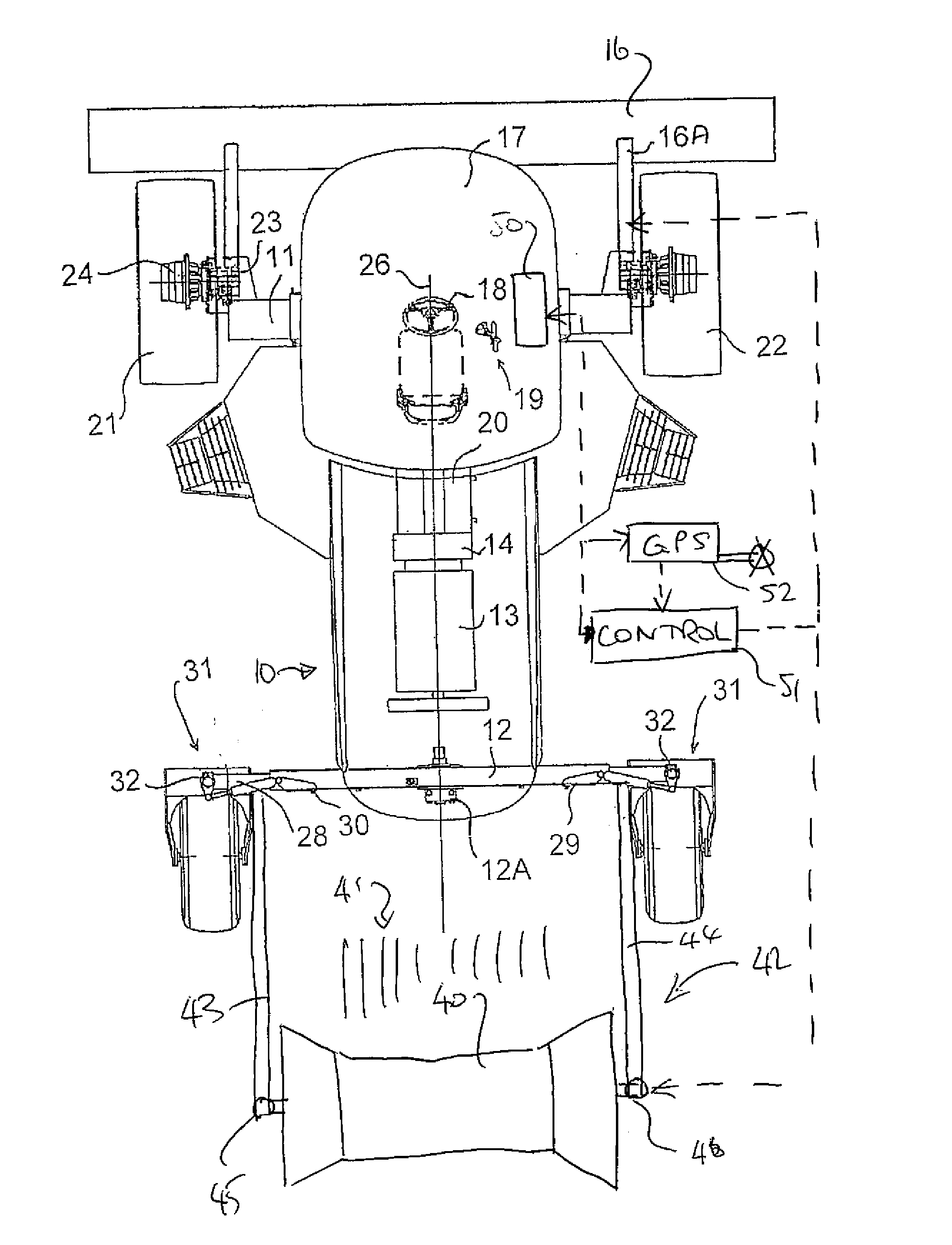
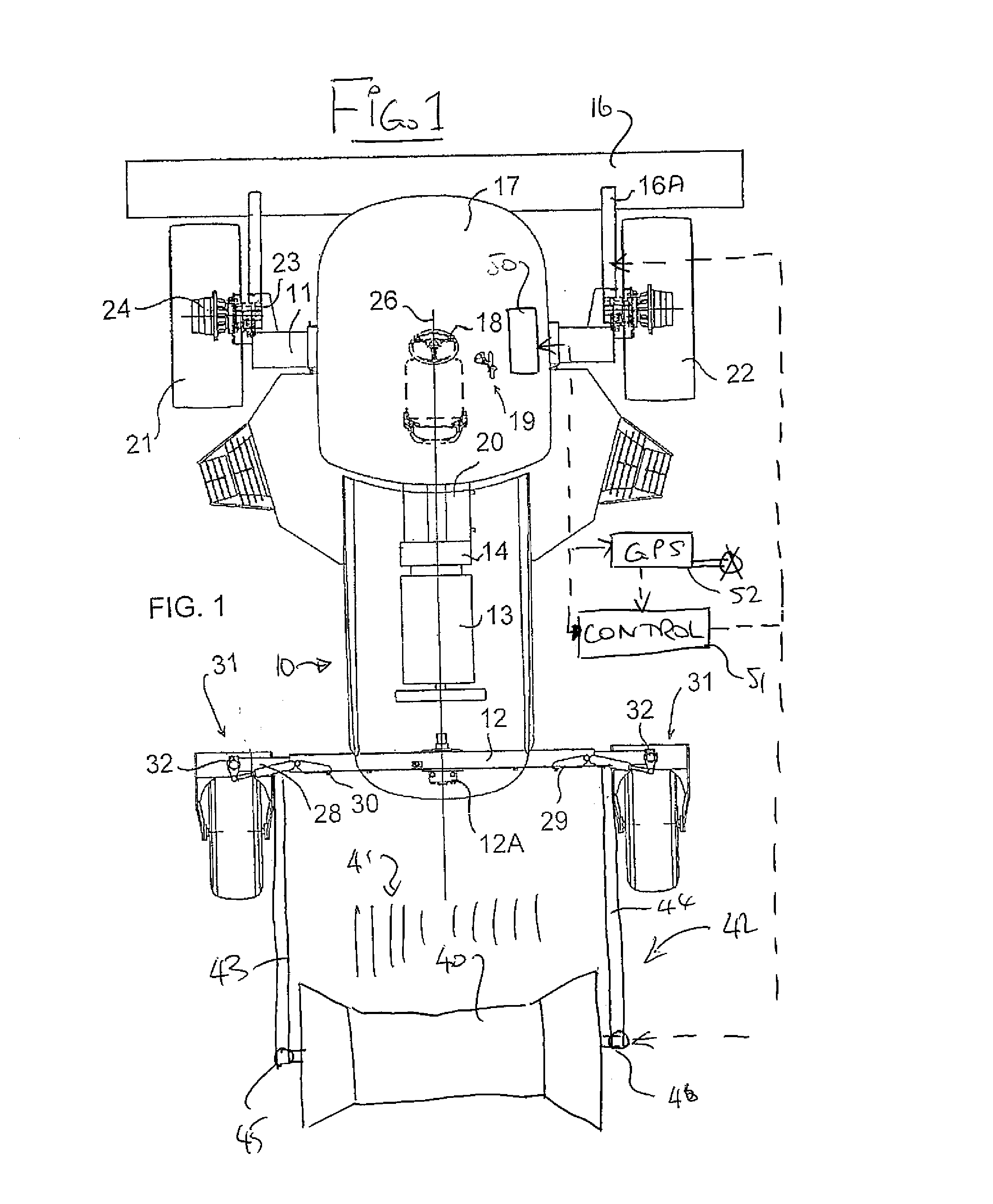
[0072]In FIG. 1 is shown a swather tractor of the above type which includes a frame 10 with a front axle 11 and a rear axle 12. On the frame 10 is mounted a motor 13 driving a gear box and pump assembly schematically indicated at 14 for communicating hydraulic drive fluid to the various components of the tractor for propelling the tractor and for driving a header 16 mounted on the tractor. In one example, the engine drives a gearbox at the rear of the engine that splits the power to two pump assemblies. One pump assembly has two pumps (one for each wheel) for traction drive and each pump controls one wheel. The other pump assembly has four pumps (two for header drive, one for lift functions and one providing supercharge oil). In the embodiment shown the header 16 for cutting a standing crop is carried on support arms 16A mounted on the tractor at the forward end in conventional manner which provide a floating and lifting actin for the header. The tractor includes a cab 17 including ...


PUM


Abstract

A swather with a crop cutting header includes a swath roller for rolling on the swath carried on a mounting assembly attached to the tractor frame and a lifting assembly for lifting the roller free from the swath where a control unit is arranged to lift the swath roller to the raised position thereof when the header is raised to the raised position thereof. The control unit also includes a GPS position sensing system so that the roller is lifted at positions determined by the GPS position sensing system. The mounting assembly comprises a mounting frame rigidly attached to the rear walking beam of the tractor so that the mounting frame is held at a set position relative to the tractor determined by a position of the beam so that the swath roller is not pivotally mounted relative to the tractor.

Description

[0001]This application claims the benefit under 35 USC 119 (e) of Provisional Application 61 / 972,724 filed Mar. 31, 2014.[0002]This invention relates to a swath roller attachment for mounting to a swather tractor for rolling over the swath behind the tractor.BACKGROUND OF THE INVENTION[0003]In U.S. Pat. No. 7,077,220 (Dunn) issued Jul. 18, 2006 and assigned to the present Assignees is disclosed a hydrostatic agricultural tractor used as a self-propelled swather tractor. This uses the typical construction for such tractors which has front ground wheels mounted on the frame at fixed angles parallel to each other and parallel to a center line of the frame and rear ground wheels mounted on a respective castor. Each of the front ground wheels is driven by a respective drive motor which allows variable speed in both the first and second directions such that steering of the tractor is effected by a differential in speed between the front wheels with, the rear wheels following the steering ...

Claims


Application Information

Patent Timeline
IPC IPC(8): A01D43/00A01D34/00A01D45/00
CPCA01D43/006A01D34/006A01D45/00A01D82/02A01D84/00
Inventor STROBBE, JASONKIRKBY, RICHARDFLINTOFT, MICHAELBARNETT, NEIL GORDON
Owner MACDON INDS
Why Eureka
Try Eureka