Ink Jet Recording Apparatus

a recording apparatus and jet technology, applied in printing and other directions, can solve the problems of increasing printing distortion and the inability to reduce the breakup distance of the liquid jet, and achieve the effect of high-speed printing

Inactive Publication Date: 2015-11-12
HITACHI IND EQUIP SYST CO LTD
View PDF2 Cites 10 Cited by
  • Summary
  • Abstract
  • Description
  • Claims
  • Application Information

AI Technical Summary

Benefits of technology

[0015]Under the circumstances, the present invention has been made to solve the above problem with droplet generation in the continuous inkjet recording apparatus, and aims at providing an ink jet recording apparatus for high velocity printing without print distortion.
[0016]According to the present invention, for the purpose of achieving the above-mentioned object, there is provided a continuous discharge type ink jet recording apparatus for recording characters or the like on an object to be recorded which moves in a direction substantially perpendicular to a deflection direction, including a unit that injects ink droplets, a unit that generates a recording signal corresponding to recording information, a unit that charges the ink droplets on the basis of the recording signal, and a unit that deflects a flying direction of the charged ink droplets, in which a unit that suppressing a velocity in the vicinity of a center axis is disposed in a unit that injects ink droplets in which because a velocity in an outer periphery is higher than that in a center of a discharged liquid column, a velocity on a surface of the liquid column becomes quickly high, and a capillary wave that propagates on a surface of the liquid column in a travel direction is quickly amplified because the velocity become quickly a velocity suitable for droplet breakup, the droplet breakup is quickly generated, and the droplet breakup is surely generated within a charging electrode located next to the nozzle. As a result, an inkjet recording apparatus stable in printing quality performance is provided.
[0018]According to the present invention, an ink jet recording apparatus and method that can perform high velocity printing without printing distortion can be realized.

Problems solved by technology

However, in the swirling flow generation structure using the spiral passage, the disturbance using an outer peripheral hole, or asymmetric heating in the nozzle exit disclosed in the above related art, the breakup distance of the liquid jet cannot be reduced.
As a result, the sufficient amount of charge is not added to the droplets, resulting in a problem that printing distortion increases.

Method used


Image

  • Ink Jet Recording Apparatus
  • Ink Jet Recording Apparatus
  • Ink Jet Recording Apparatus

Examples


embodiments

[0030]First, a description will be given of an overall configuration of an ink jet recording apparatus according to the present invention.

[0031]FIG. 7 is an overall configuration diagram illustrating an ink jet recording apparatus according to the present invention. Referring to FIG. 7, an ink jet recording apparatus includes an ink jet drive unit, an ink concentration control unit, and a recording medium transport control unit.

[0032]The ink jet drive unit includes an ink jet head 32, a liquid reservoir 43, an AC power supply 47 which supplies AC voltage to a piezoelectric element within the inkjet head 32, a control voltage power supply 33 which applies a voltage to a charging electrode for supplying electric charge to respective droplets, and a deflection electrode for deflecting the droplets, pumps 46 and 36 which perform supply and recovery of the liquid with respect to the ink jet head 32, and a main control unit 37 that controls the operation of the respective units.

[0033]Also...

first embodiment

[0038]An embodiment of the present invention as described below is applied to a continuous discharge type ink jet recording apparatus among the ink jet recording apparatus illustrated in FIG. 7.

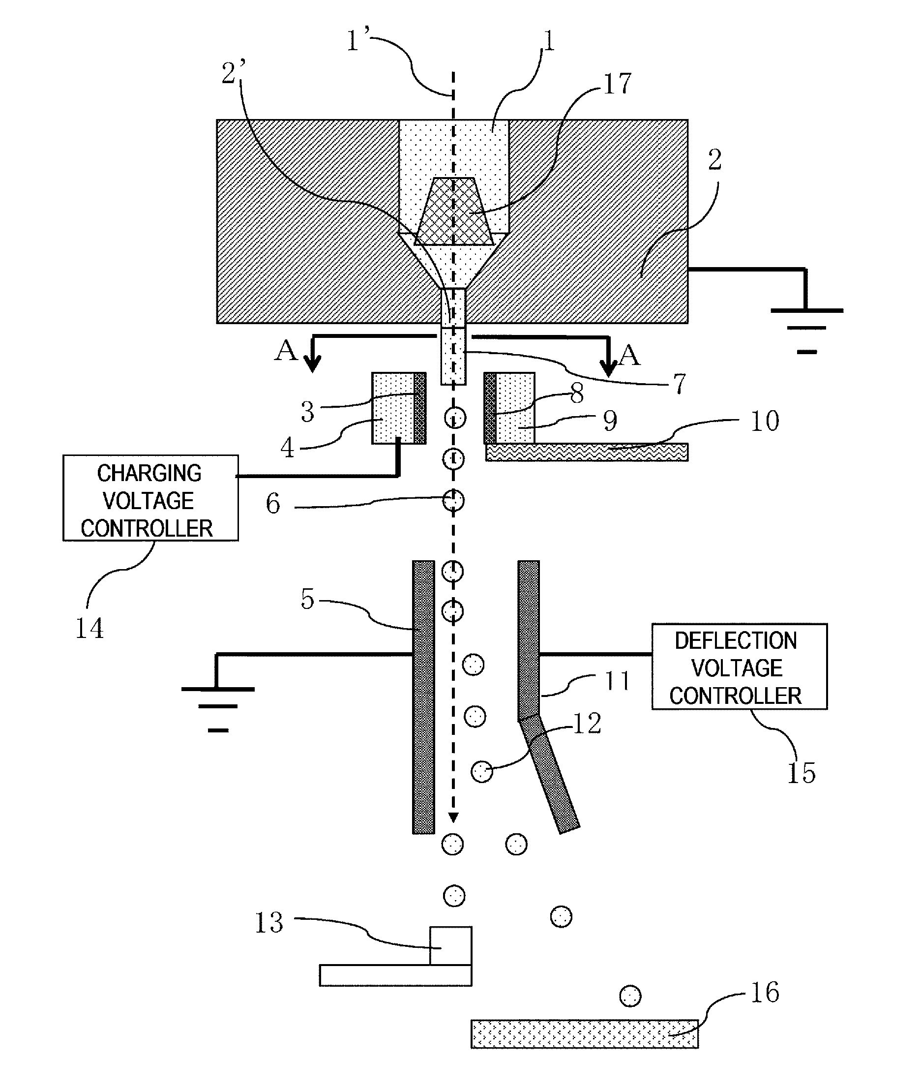
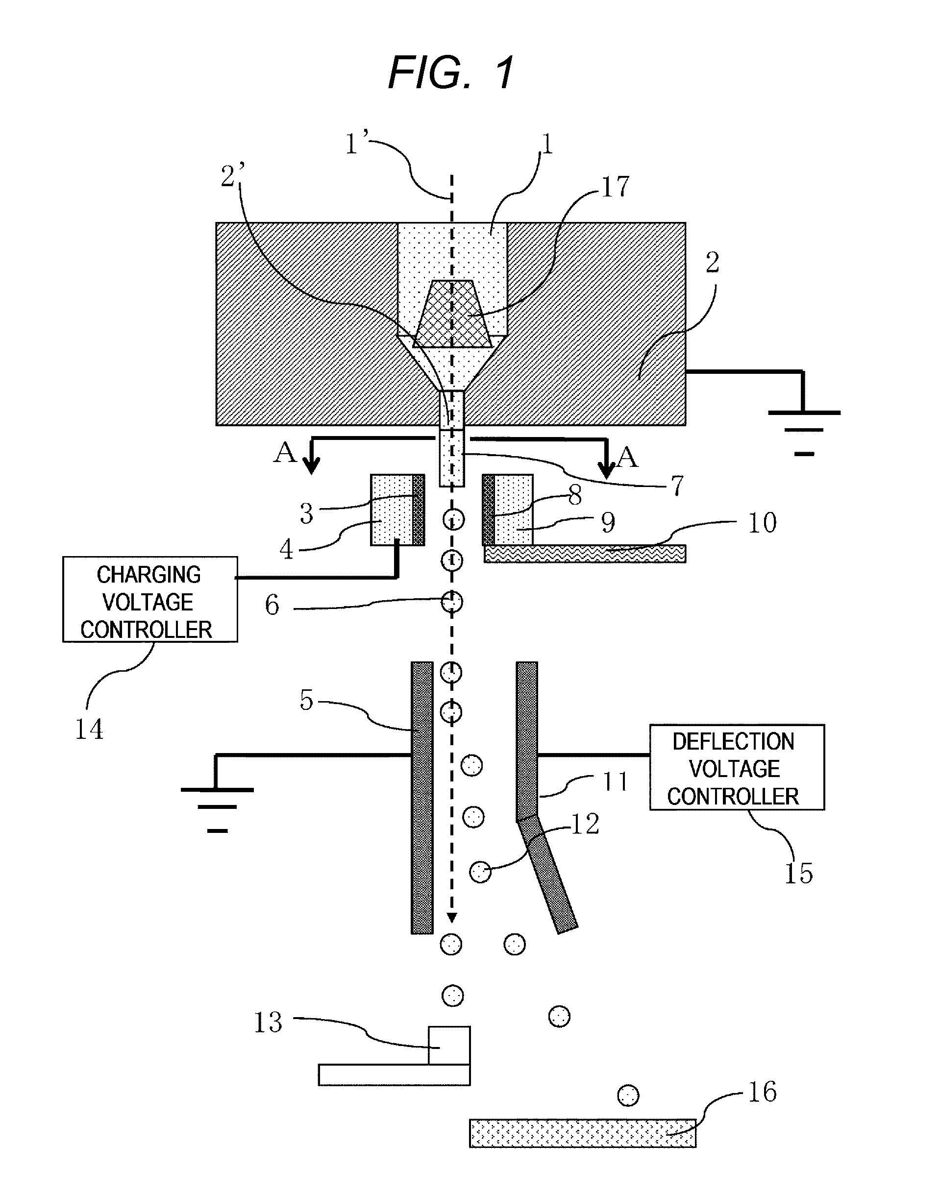
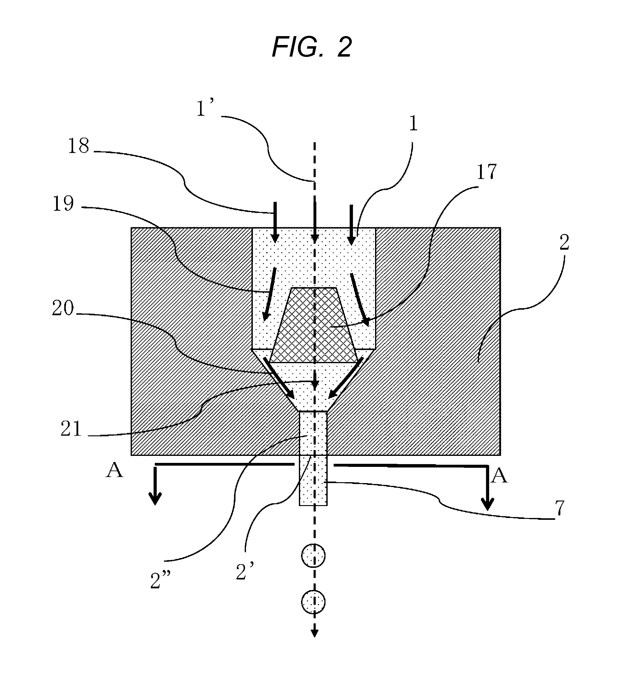
[0039]A description will be given of a general structure of a nozzle in an ink jet heat in the continuous discharge type ink jet recording apparatus (or continuous ink jet recording apparatus) according to the first embodiment of the present invention with reference to FIGS. 1, 2, 3, and 4.

[0040]FIG. 1 is a configuration diagram of a main portion of the first embodiment of the present invention, which is a diagram illustrating an internal configuration of the inkjet head 32 in FIG. 7. FIG. 2 is a configuration diagram of a main portion of a nozzle head 2, and FIG. 3 is an illustrative diagram of the details of a change in a velocity distribution of ink in a traveling direction, which is close to a cross-section A-A in the vicinity of an exit of an ink chamber 1 in FIG. 1. FIG. 4 is a configur...

second embodiment

[0054]Subsequently, a second embodiment of the present invention will be described.

[0055]FIG. 5 is a configuration diagram illustrating a main portion of a second embodiment of the present invention. The other configurations not illustrated in FIG. 5 are equivalent to those in the example of FIG. 1. Referring to FIG. 5, the axis vicinity speed suppression unit 17 is formed in a conical shape a cross-sectional area of which decreases in a traveling direction. With this configuration, since a protruding end of the cone is brought close to the nozzle exit 2′, a concave type velocity distribution with a reduction in a velocity in the vicinity of the center axis can be generated, and the breakup distance can be shortened.


PUM


Abstract

An ink jet recording apparatus that can perform high velocity printing without printing distortion is realized. In a continuous discharge type ink jet recording apparatus, a unit that suppresses a velocity in the vicinity of a center axis is disposed in a unit that injects ink droplets in which because a velocity in an outer periphery is higher than that in a center of a discharged liquid column, a velocity on a surface of the liquid column becomes quickly high, and a capillary wave that propagates on a surface of the liquid column in a travel direction is quickly amplified because the velocity becomes quickly a velocity suitable for droplet breakup, the droplet breakup is quickly generated, and the droplet breakup is surely generated within a charging electrode located next to the nozzle. As a result, an ink jet recording apparatus stable in printing quality performance is provided.

Description

BACKGROUND OF THE INVENTION[0001]1. Technical Field[0002]The present invention relates to an ink jet recording apparatus.[0003]2. Description of the Related Art[0004]Among ink jet recording apparatuses, a continuous discharge type inkjet recording apparatus is a highly stable droplet discharge device having a high maintainability and a high reliability as compared with an on-demand type ink jet recording apparatus used in a domestic or office printer. Therefore, the continuous discharge type ink jet recording apparatuses are used on many production lines for printing on various types of products such as cans, bottles, packages, and food packaging.[0005]For that reason, the continuous discharge type ink jet recording apparatus can be also applied to a manufacturing device for electronic equipment requiring function ink coating or pattering using liquid which requires high reliability, high maintenance, and high stability. Also, the continuous discharge type ink jet recording apparatu...

Claims


Application Information

Patent Timeline
Patent Type & Authority Applications(United States)
IPC IPC(8): B41J2/02
CPCB41J2/02B41J2002/14475
Inventor IKEGAWA, MASATOISHII, EIJIHARADA, NOBUHIROMIYAO, AKIRA
Owner HITACHI IND EQUIP SYST CO LTD
Why Eureka
Try Eureka