Base, liquid discharge head, printing apparatus, and method for determining liquid discharge status

a liquid discharge head and printing apparatus technology, applied in printing, other printing apparatus, etc., can solve the problems of inability to accurately determine the liquid discharge status, the circuit scale is large, and the process takes time to complete, so as to achieve accurate liquid discharge status determination and simple arrangement

Active Publication Date: 2015-11-12
CANON KK
View PDF7 Cites 7 Cited by
  • Summary
  • Abstract
  • Description
  • Claims
  • Application Information

AI Technical Summary

Benefits of technology

[0017]The invention is particularly advantageous since it is possible to accurate

Problems solved by technology

In this liquid discharge head, ink discharge failure may occur in all or some nozzles of the liquid discharge head due to nozzle clogging caused by a foreign substance, ink of high viscosity, or the like, a bubble entering an i

Method used


Image

  • Base, liquid discharge head, printing apparatus, and method for  determining liquid discharge status
  • Base, liquid discharge head, printing apparatus, and method for  determining liquid discharge status
  • Base, liquid discharge head, printing apparatus, and method for  determining liquid discharge status

Examples


first embodiment

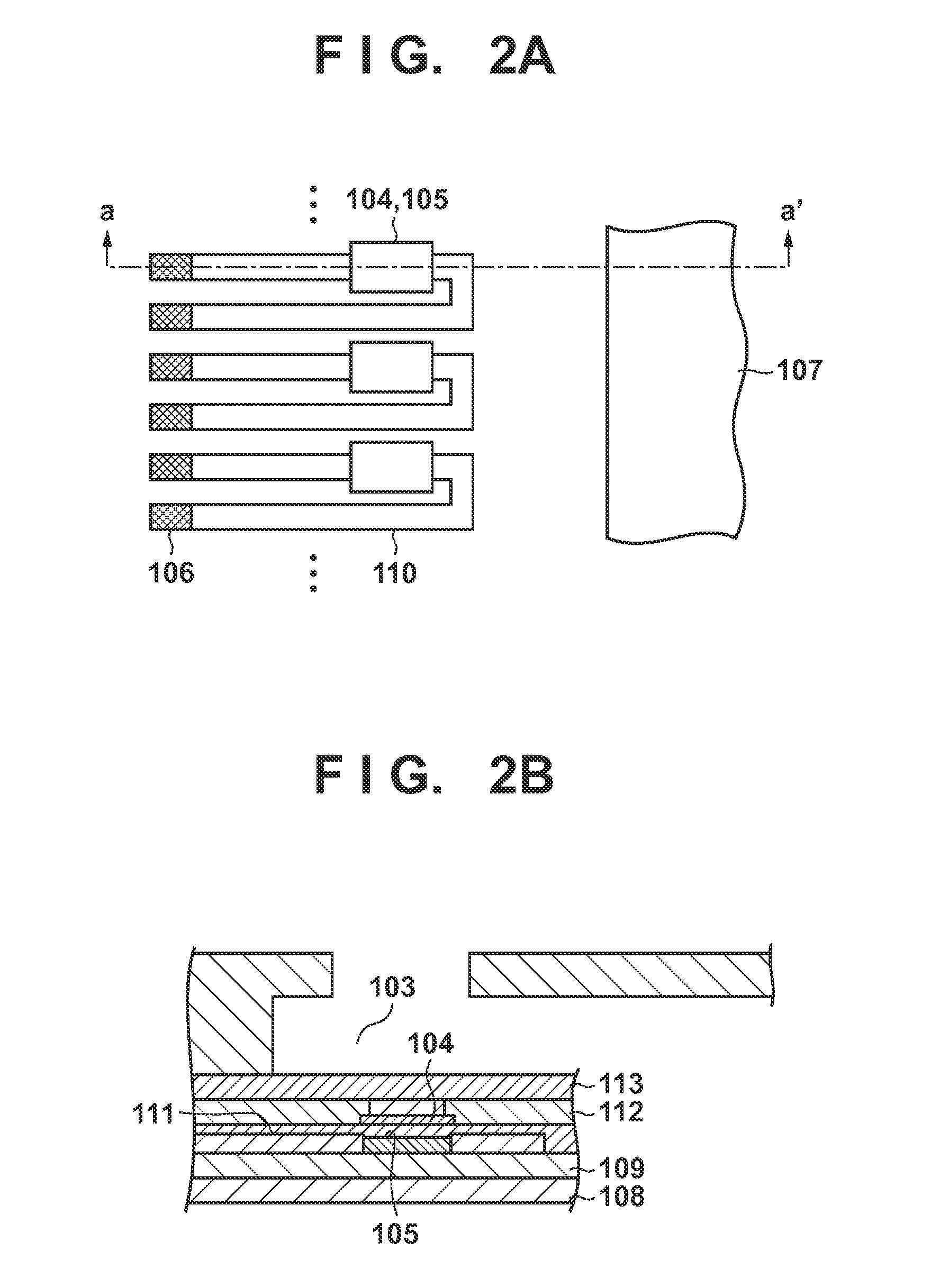
[0071]FIGS. 6A and 6B are a side sectional view and plan view, respectively, showing the arrangement of temperature detection elements and a heater according to the first embodiment of the present invention.

[0072]As shown in FIGS. 6A and 6B, in this embodiment, two temperature detection elements (temperature sensors) 105A and 105B are provided for one heater. The two temperature detection elements (temperature sensors) formed as film resistors as described above are arranged immediately below one heater 104. This makes it possible to measure the temperature at two positions immediately below the heater, at which temperature changes are different from each other.

[0073]As shown in FIG. 6A, an interconnection connected to each temperature detection element is connected to an interconnection 110 in a layer different from that of the temperature detection element across the layer. By providing the interconnection in another layer, heat transferred via the interconnection between the two ...

second embodiment

[0086]In this embodiment, a case in which the temperature detection circuit described in the first embodiment is driven by using two electric current supply sources will be explained.

[0087]FIG. 10 is a circuit diagram showing the arrangement of a temperature detection circuit according to the second embodiment of the present invention.

[0088]The same reference numerals as those in FIG. 7 denote the same components inFIG. 10 and a description thereof will be omitted. As will be apparent by comparing FIGS. 10 and 7 with each other, in this embodiment, individual electric current supply sources 120A and 120B are provided for respective two temperature detection elements. In this embodiment, therefore, it is possible to control the electric current of each temperature detection element.

[0089]FIGS. 11A and 11B are graphs each showing temporal changes in output voltages from the two temperature detection elements in a case where an electric current supplied from the electric current supply...

third embodiment

[0096]In this embodiment, a case in which the ink discharge status is detected according to a voltage difference between two temperature detection elements will be described.

[0097]As described above, in normal ink discharge, part of a discharged ink droplet comes into contact with the surface of an anti-cavitation film 113, and thus a temperature difference between a portion immediately below the center of a heater 104 and a portion immediately below the periphery of the heater 104 becomes small. On the other hand, in ink discharge failure, the center and periphery of the heater 104 are in contact with air, the temperature difference between the portion immediately below the center and the portion immediately below the periphery does not become small, unlike normal discharge. In this embodiment, the ink discharge status is detected by detecting the magnitude of the temperature difference.

[0098]FIG. 13 is a circuit diagram showing the arrangement of a temperature detection circuit ac...


PUM


Abstract

An embodiment of this invention is directed to determining a discharge status of liquid discharged from a liquid discharge head capable of accurately determining the discharge status of each nozzle at high speed with a simple arrangement. According to the embodiment, a base includes an electrothermal transducer configured to supply heat to liquid, a first temperature detection element configured to detect the temperature of the electrothermal transducer, and a second temperature detection element configured to detect the temperature of the same electrothermal transducer. In this case, the first and the second temperature detection elements are arranged so that at least part of each of the first and second temperature detection elements is included immediately above or below a region where the electrothermal transducer is arranged in the base.

Description

BACKGROUND OF THE INVENTION[0001]1. Field of the Invention[0002]The present invention relates to a base, a liquid discharge head, a printing apparatus, and a method for determining an ink discharge status and, particularly, to a printing apparatus which uses a liquid discharge head including heating elements (heaters) for discharging liquid such as ink, and a method for determining a liquid discharge status.[0003]2. Description of the Related Art[0004]One of inkjet printing methods for discharging ink droplets from nozzles and adhering them to a print medium such as paper or a plastic film uses a liquid discharge head including heaters configured to generate heat energy for discharging ink. For the liquid discharge head according to this method, an electrothermal transducer which generates heat in accordance with energization, a driving circuit, and the like can be formed by a process similar to a semiconductor manufacturing process. Therefore, high-density integration of nozzles is...

Claims


Application Information

Patent Timeline
IPC IPC(8): B41J2/045B41J2/14
CPCB41J2/0454B41J2/04585B41J2/14427B41J2/0451B41J2/04563B41J2/0458B41J2002/14354B41J2/14153
Inventor IKE, TAKESHI
Owner CANON KK
Why Eureka
Try Eureka