
Vehicular battery system and vehicle equipped with same

a battery system and vehicle technology, applied in the field of battery systems, can solve the problems of increasing the current carrying capacity of the dc/dc converter, complicated circuit construction, and increasing the cost of parts or manufacturing, so as to prolong the life of the lead battery, improve the fuel efficiency of the vehicle, and efficient charge

Active Publication Date: 2015-11-12
SANYO ELECTRIC CO LTD
View PDF2 Cites 10 Cited by
  • Summary
  • Abstract
  • Description
  • Claims
  • Application Information

AI Technical Summary

Benefits of technology

The present invention is a battery system for a vehicle that prevents degradation of the lead battery and makes it last longer. The system includes a circuit construction that is simple and efficient in charging the sub-battery with regenerative braking, which improves fuel efficiency and protects the lead battery from large charging currents. The technical effects of this invention are to prolong the life of the lead battery and improve the overall performance of the vehicle's battery system.

Problems solved by technology

In this battery system, as the sub-battery is connected in parallel through the DC / DC converter, circuit construction is complicate, and parts cost, or manufacturing cost is increased as the demerit.
Especially, when this battery system is installed in the vehicle having an idle stop function, and both the lead battery and the sub-battery are charged by generation power of regenerative braking, it is necessary that a current carrying capacity of the DC / DC converter is very large, and then it remarkably increases parts cost of the DC / DC converter, manufacturing cost.
In the battery system in which the sub-battery is connected through the DC / DC converter, it is difficult to efficiently charge the sub-battery by generation power of regenerative braking.
It is a reason why power loss in the DC / DC converter decreases the charging power of the sub-battery.
However, even in this battery system, as adaptability of the lead battery and the sub-battery is not enough, the battery system is not efficiently charged by generation power of regenerative braking, and fuel efficiency cannot be improved enough by regenerative braking.

Method used


Image

  • Vehicular battery system and vehicle equipped with same
  • Vehicular battery system and vehicle equipped with same
  • Vehicular battery system and vehicle equipped with same

Examples


Embodiment Construction

[0043]Hereinafter, the embodiment of the present invention will be described referring to drawings. However, the following embodiments illustrate a battery system for a vehicle, and a vehicle equipped with the battery system which are aimed at embodying the technological concept of the present invention, and the present invention is not limited to the battery system for the vehicle, and the vehicle equipped with the battery system described below. However, the members illustrated in Claims are not limited to the members in the embodiments.

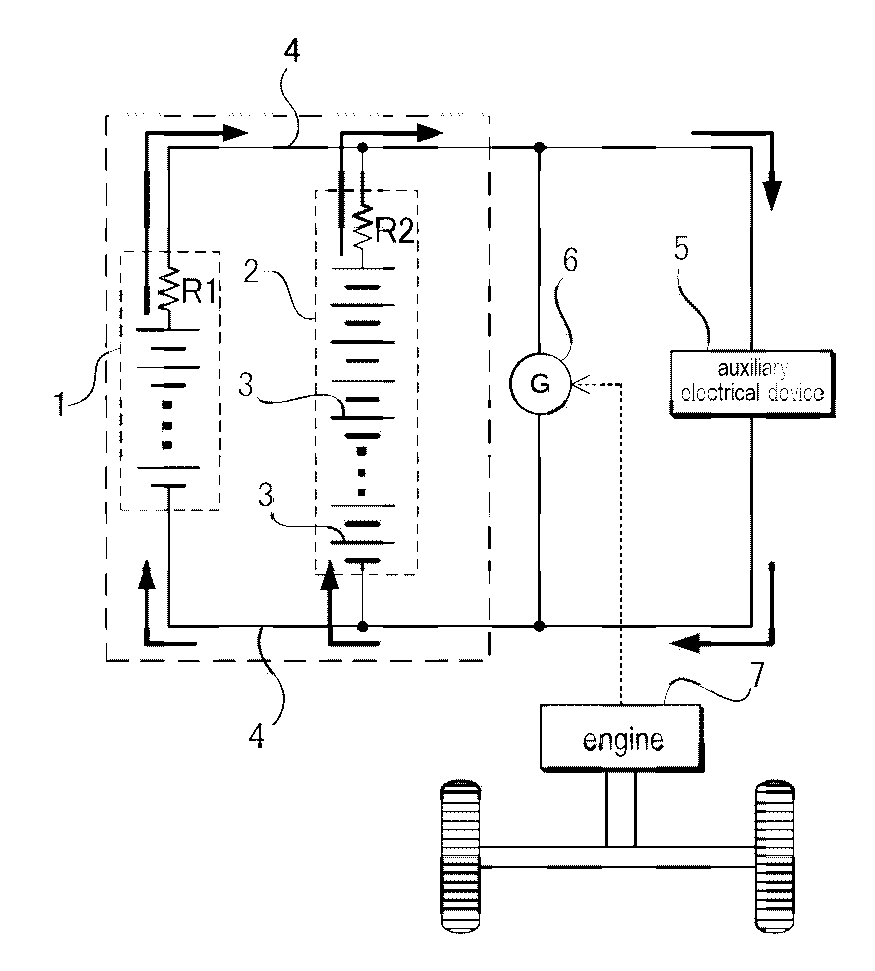
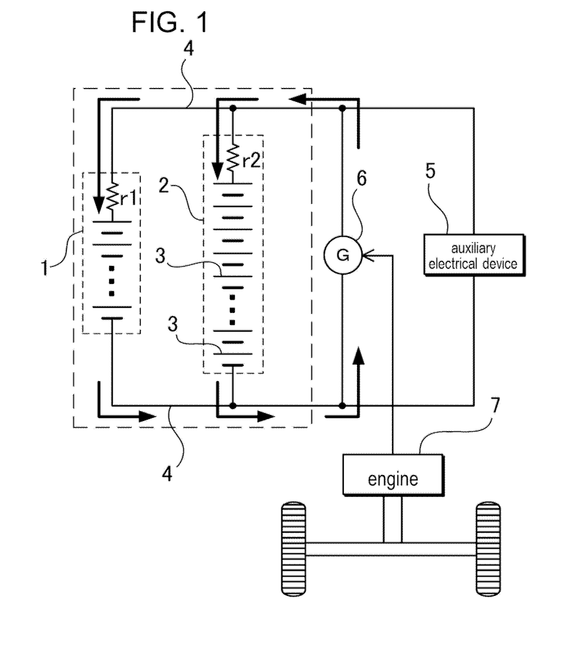
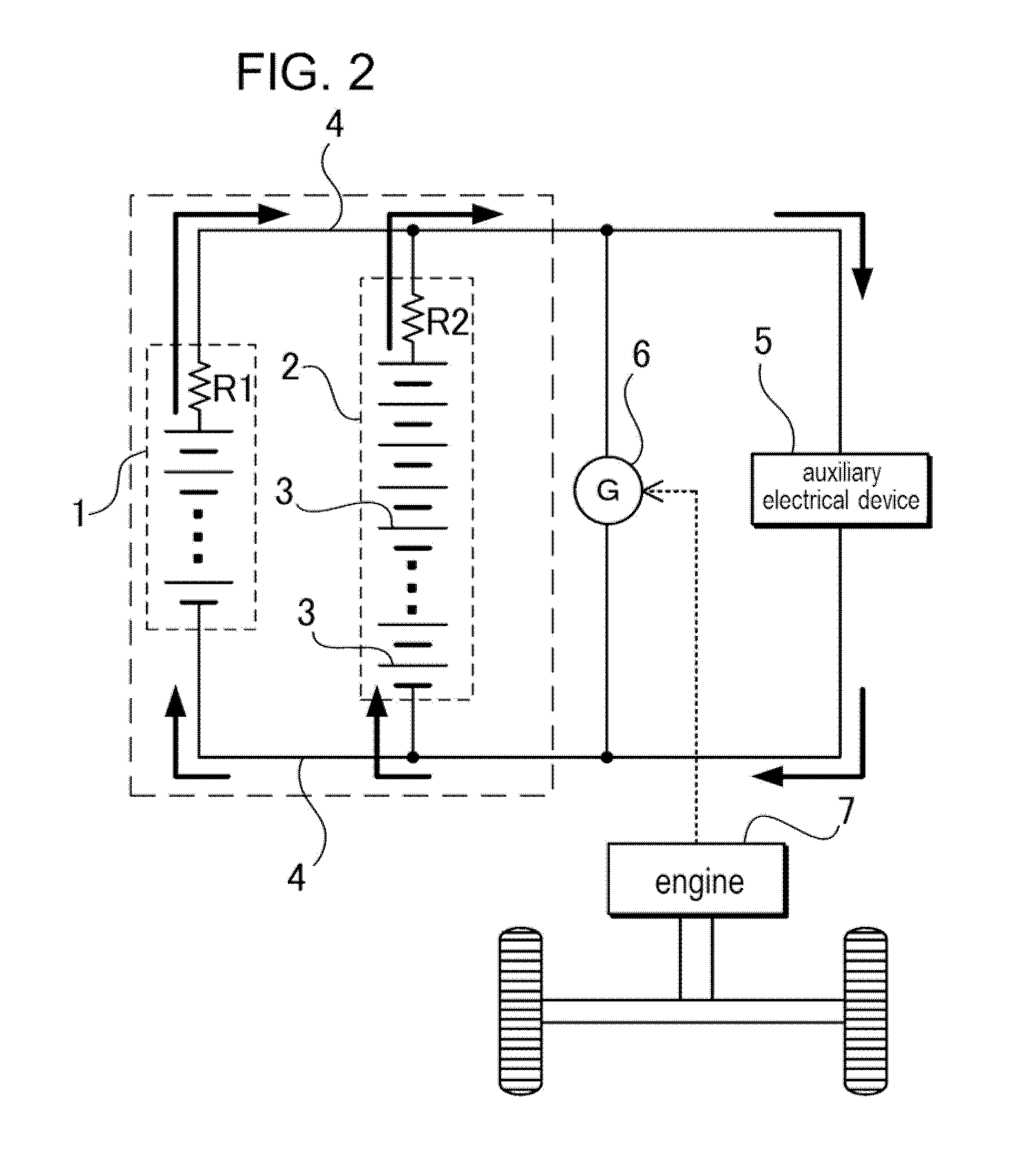
[0044]In the battery system for a vehicle shown in FIG. 1, a lead battery 1 and a sub-battery 2 are connected in parallel. The lead battery 1 and the sub-battery 2 are directly connected by a lead wire 4 without a current adjusting circuit or the like. Therefore, the lead battery 1 and the sub-battery 2 always have the same voltage. But in the battery system, the lead battery and the sub-battery can be connected in parallel through relays, semicond...


PUM


Abstract

In a battery system for a vehicle, a lead battery is connected in parallel to a sub-battery, and a charging resistance r2 of the sub-battery 2 is lower than a charging resistance r1 of the lead battery.

Description

CROSS-REFERENCE TO RELATED APPLICATIONS[0001]The present application is a U.S. national stage application of PCT International Application No. PCT / JP2012 / 080909 filed on Nov. 29, 2012, and claims the benefit of foreign priority of Japanese Patent Application No. 2012-195250 filed on Sep. 5, 2012, the contents all of which are incorporated herein by reference.TECHNICAL FIELD[0002]The present invention is related to a battery system for a vehicle in which a lead battery and a sub-battery are connected in parallel, and a vehicle equipped with the battery system.BACKGROUND ART[0003]In a conventional vehicle, as an auxiliary battery, a lead battery having a rated voltage of 12V is installed. Further, in a large vehicle, a battery having a rated voltage of 24 V by connecting two of the lead batteries of 12V in series is installed. The lead battery is charged by an alternator in the vehicle, and supplies electric power to auxiliary electrical devices in the vehicle, a starter motor, or the...

Claims


Application Information

Patent Timeline
IPC IPC(8): B60L11/18
CPCB60L11/1859B60L11/1868B60L11/1816B60L53/14B60L58/20H02J7/1423Y02T10/70Y02T10/7072Y02T90/14B60L58/14
Inventor SAKATANI, TOSHIHIROSUGII, HIROMASAOCHI, MAKOTOKAWASE, RYUUJI
Owner SANYO ELECTRIC CO LTD
Learn More