Systems and methods for controlling conditioned fluid systems in a built environment

a technology of conditioned fluid and built environment, which is applied in the direction of air heaters, heating types, lighting and heating apparatus, etc., can solve the problems of not addressing the distribution of conditioned fluid, 20% of the remaining units are either too hot or too cold,

Active Publication Date: 2015-11-12
GLUCK JERRITT L
View PDF3 Cites 26 Cited by
  • Summary
  • Abstract
  • Description
  • Claims
  • Application Information

AI Technical Summary

Problems solved by technology

This means that about 20% of the remaining units are either too hot or too cold.
However, these improvements do not address the distribution of conditioned fluid.

Method used


Image

  • Systems and methods for controlling conditioned fluid systems in a built environment
  • Systems and methods for controlling conditioned fluid systems in a built environment
  • Systems and methods for controlling conditioned fluid systems in a built environment

Examples


Embodiment Construction

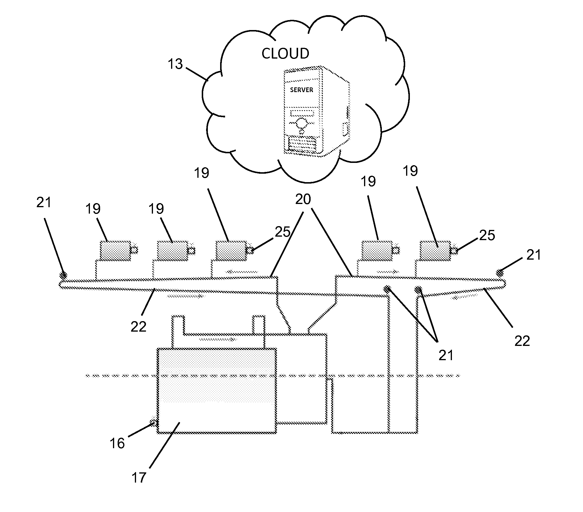
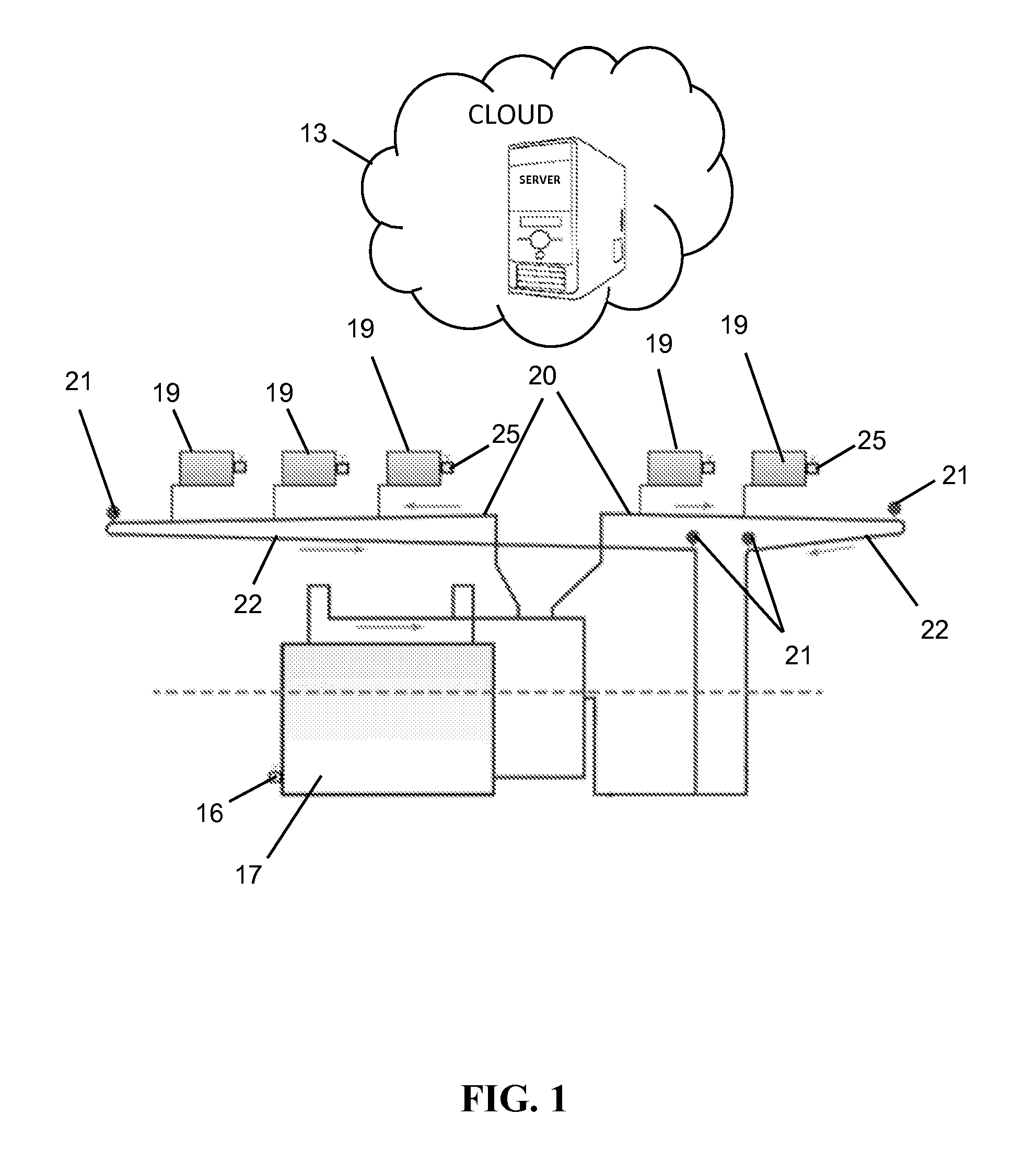
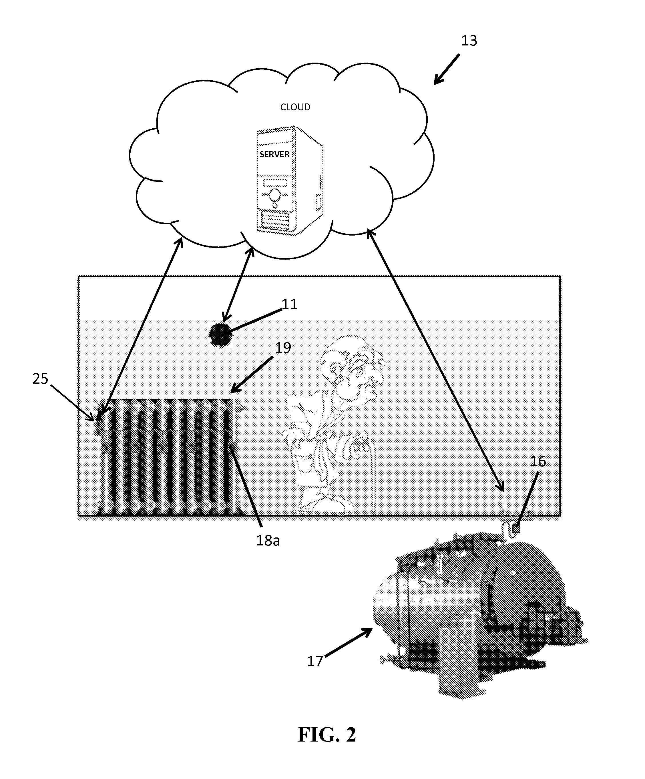
[0029]The systems and methods of this disclosure dynamically redistribute heating and cooling to those rooms that require conditioned air, e.g., those rooms that are occupied. To accomplish this, the systems and methods of this disclosure control the flow rate of conditioned fluid (e.g., air, steam, or water) through a thermal distribution device (e.g., a steam radiator, a low mass radiator, a hydronic baseboard radiator, or a diffuser of a forced-air heating and cooling system) to selectively heat or cool individual rooms of a commercial or residential structure or building to different temperature setpoints.

[0030]In the case of steam heating, a server transmits a first control signal to a radiator controller to control an electromechanical air vent to cause a desired amount of steam to flow into a steam radiator in order to achieve a desired temperature setpoint. The server also transmits a second control signal to a steam source to control or modulate the flow rate of the steam o...


PUM


Abstract

The systems and methods of this disclosure control the flow rate of conditioned fluid at thermal distribution devices and at a conditioned fluid source that supplies conditioned fluid to the thermal distribution devices. The systems include multiple thermal distribution devices disposed throughout multiple rooms of a building, a fluid flow control device in fluid communication with each of the thermal distribution devices, multiple sensors disposed on each of the thermal distribution devices, a room temperature sensor disposed in each of the rooms, a first controller coupled to each of the fluid flow control devices, and a second controller coupled to a source of conditioned fluid. The first controllers control respective fluid flow control devices based on the measurement data obtained from the sensors and the room temperature sensors and a second controller controls the conditioned fluid source based on the demand for conditioned fluid by the thermal distribution devices.

Description

BACKGROUND[0001]1. Technical Field[0002]This disclosure generally relates to systems and methods for controlling conditioned fluid systems in a built environment. In particular, the systems and methods of this disclosure wirelessly control the flow rate of conditioned fluid at thermal distribution devices and at the conditioned fluid source that supplies conditioned fluid to the thermal distribution devices.[0003]2. Background of Related Art[0004]Traditionally, apartments or commercial buildings, especially small buildings up to three stories, used a single thermostat with a temperature setpoint to activate the boiler to burn fuel and thereby produce steam for heating the building. All subsequent steam heat strategies are built from this principle.[0005]One strategy is to place a number of sensors, e.g., six temperature sensors, on the top floor of a building in residential units to collect temperature data. This data is then averaged and the boiler runtime is adjusted to maintain a...

Claims


Application Information

Patent Timeline
Patent Type & Authority Applications(United States)
IPC IPC(8): F24D19/10F24D1/02
CPCF24D1/02F24D19/1003F24D5/04F22B5/00F22B35/18Y02B30/00F24H15/464F24H15/238F24H15/36F22B1/00
Inventor GLUCK, JERRITT L.OSHER, LASZLO
Owner GLUCK JERRITT L
Why Eureka
Try Eureka