
Dynamic measurement of material properties using terahertz radiation with real-time thickness measurement for process control

a technology of terahertz radiation and process control, applied in the direction of optical radiation measurement, material analysis, instruments, etc., can solve the problems of affecting the quality of final products, so as to achieve the effect of fast and efficien

Inactive Publication Date: 2015-11-12
ADVANTEST CORP
View PDF8 Cites 21 Cited by
  • Summary
  • Abstract
  • Description
  • Claims
  • Application Information

AI Technical Summary

Benefits of technology

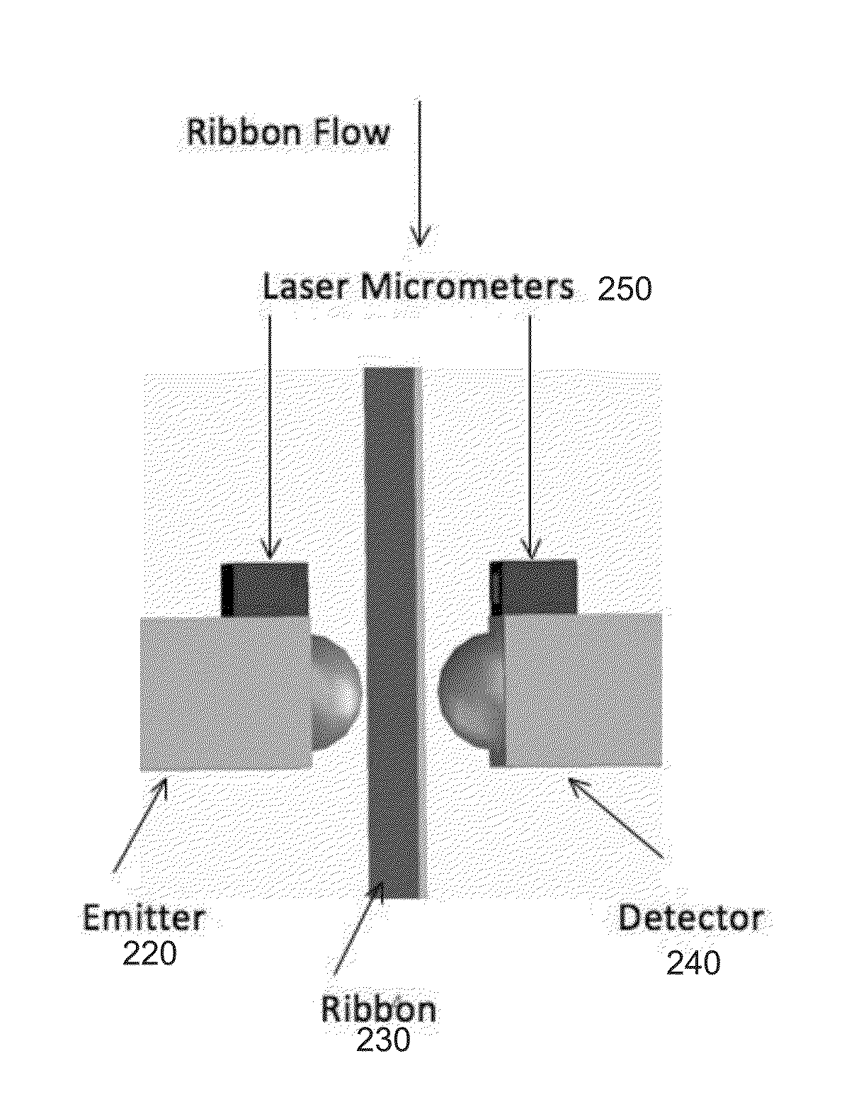
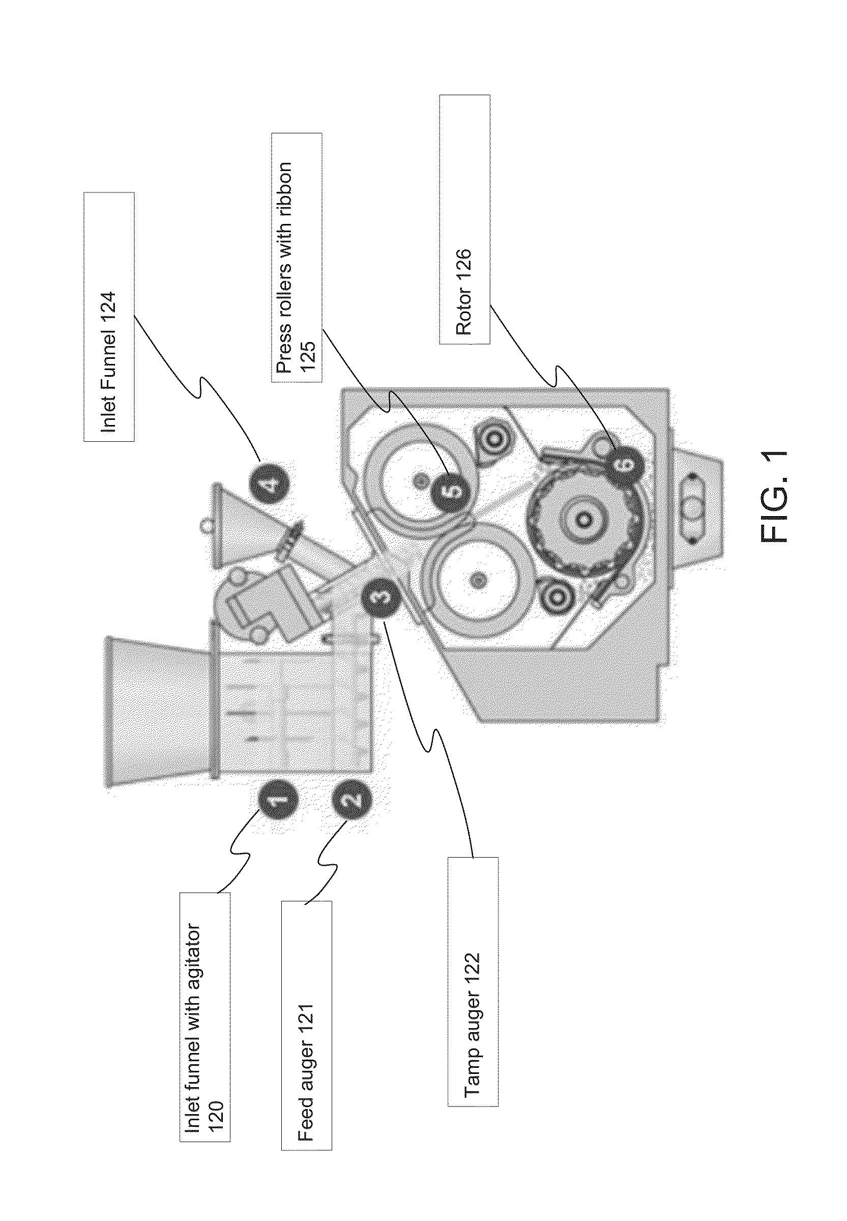
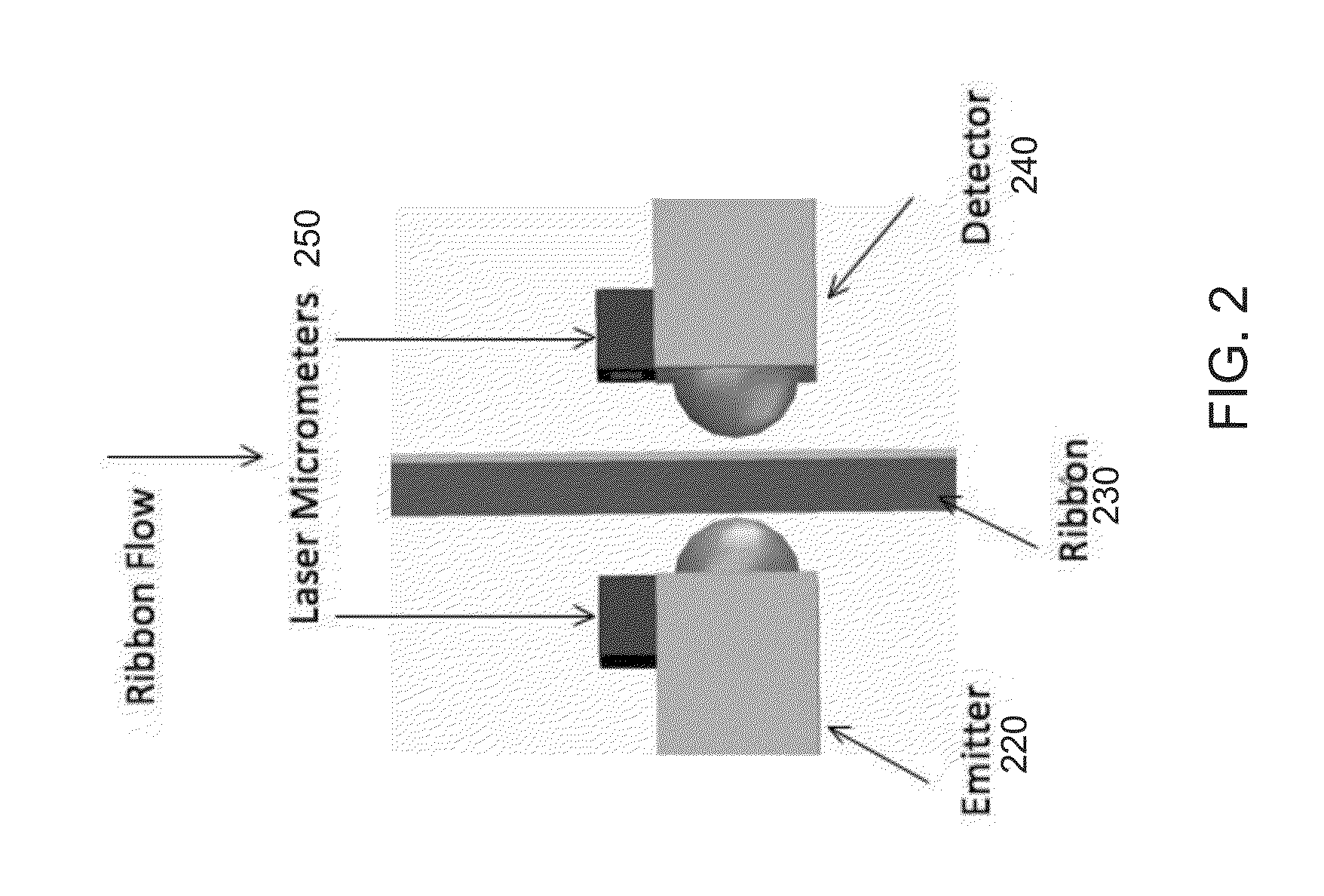
The patent text describes a need for a faster and more efficient way to measure the optical and material properties of materials, such as pharmaceutical ribbons, during production or testing processes. The text describes a tester system that uses terahertz time-domain spectroscopy (THz-TDS) to non-invasively measure the refractive index, absorption coefficient, permittivity, dielectric loss, and other properties of materials in real-time. The system includes a laser micrometer to determine the thickness of the material at a point on the object, and a THz emitter and detector to obtain the optical properties. The system can be used in various industrial processes to measure the properties of materials during production or testing.

Problems solved by technology

When the powder blend is compacted by applying force to the powder, it results in considerable size enlargement.
However, because it is inefficient, it is rarely used.
For example, the powders may not possess enough natural flow to feed the product uniformly, resulting in various degrees of density in the final product.
Changes in ribbon density typically cause large fluctuations in granulate properties.
Microindentation hardness testing is not ideal because it is slow and invasive and, therefore, not suited for on-line testing.
Because microindentation hardness testing is not an on-line method, the time period between the test and analysis to verify the density of the ribbon is long.
This can lead to significant delays and a large amount of wasted product if the problem is detected too far into the process.
Similar to pharmaceutical ribbons, determining optical and material properties of other materials dynamically in an on-line process is challenging.
Prior methods of performing measurements for determining the material properties have been inadequate because they are either invasive, static, or involve significant delays.

Method used


Image

  • Dynamic measurement of material properties using terahertz radiation with real-time thickness measurement for process control
  • Dynamic measurement of material properties using terahertz radiation with real-time thickness measurement for process control
  • Dynamic measurement of material properties using terahertz radiation with real-time thickness measurement for process control

Examples


Embodiment Construction

[0034]Reference will now be made in detail to the various embodiments of the present disclosure, examples of which are illustrated in the accompanying drawings. While described in conjunction with these embodiments, it will be understood that they are not intended to limit the disclosure to these embodiments. On the contrary, the disclosure is intended to cover alternatives, modifications and equivalents, which may be included within the spirit and scope of the disclosure as defined by the appended claims. Furthermore, in the following detailed description of the present disclosure, numerous specific details are set forth in order to provide a thorough understanding of the present disclosure. However, it will be understood that the present disclosure may be practiced without these specific details. In other instances, well-known methods, procedures, components, and circuits have not been described in detail so as not to unnecessarily obscure aspects of the present disclosure.

[0035]S...


PUM

PropertyMeasurementUnit
thickaaaaaaaaaa
thickaaaaaaaaaa
thickaaaaaaaaaa

Abstract

A method of determining material properties for an object under test is disclosed. The method comprises determining a thickness at a point on the object under test in a non-invasive manner. It also comprises obtaining a terahertz measurement by passing terahertz radiation through the object under test using a terahertz emitter and detecting the terahertz radiation using a terahertz detector. Finally, it comprises determining an optical property at the point on the object under test using a measurement value from the terahertz emitter and the terahertz detector and a measured value for the thickness at the point.

Description

CROSS-REFERENCE TO RELATED APPLICATIONS[0001]The present application is a continuation in part of and claims priority to and the benefit of co-pending, commonly owned, U.S. patent application Ser. No. 14 / 273,252, entitled “Dynamic Measurement of Density Using Terahertz Radiation With Real-Time Thickness Measurement For Process Control,” having a filing Date of May 8, 2014, and having attorney docket number ATSY-0017-01.01US.FIELD OF THE INVENTION[0002]Embodiments according to the present invention generally relate to automated test equipment and, more specifically, to performing measurements using terahertz (THz) spectroscopy in automated test equipment.BACKGROUND OF THE INVENTION[0003]Automated test equipment (ATE) relates to any testing assembly that performs a test on a device or material under test. ATE assemblies may be used to execute automated tests that quickly perform measurements and generate test results that can then be analyzed. An ATE assembly may be anything from a co...

Claims


Application Information

Patent Timeline
Patent Type & Authority Applications(United States)
IPC IPC(8): G01N21/3586G01N21/3563G01B11/06G01N33/15
CPCG01N21/3586G01N33/15G01N2201/0692G01B11/06G01N2201/061G01N21/3563
Inventor KING, EDWARDHEAPS, DAVIDSULLIVAN, MARKMCKAY, RICHARDKATO, EIJI
Owner ADVANTEST CORP
Learn More