Radar system and method for determining range, relative velocity and bearing of an object using continuous-wave and chirp signals

a technology applied in the field of chirp signal and chirp signal, can solve problems such as difficulty in eliminating ambiguities in range and velocity information

Active Publication Date: 2015-11-12
ARRIVER SOFTWARE LLC (N D GES D STAATES DELAWARE)
View PDF1 Cites 96 Cited by
  • Summary
  • Abstract
  • Description
  • Claims
  • Application Information

AI Technical Summary

Problems solved by technology

However, it can be difficult to eliminate ambiguities among range and velocity information, particularly in the presence of multiple objects.

Method used


Image

  • Radar system and method for determining range, relative velocity and bearing of an object using continuous-wave and chirp signals
  • Radar system and method for determining range, relative velocity and bearing of an object using continuous-wave and chirp signals
  • Radar system and method for determining range, relative velocity and bearing of an object using continuous-wave and chirp signals

Examples


Embodiment Construction

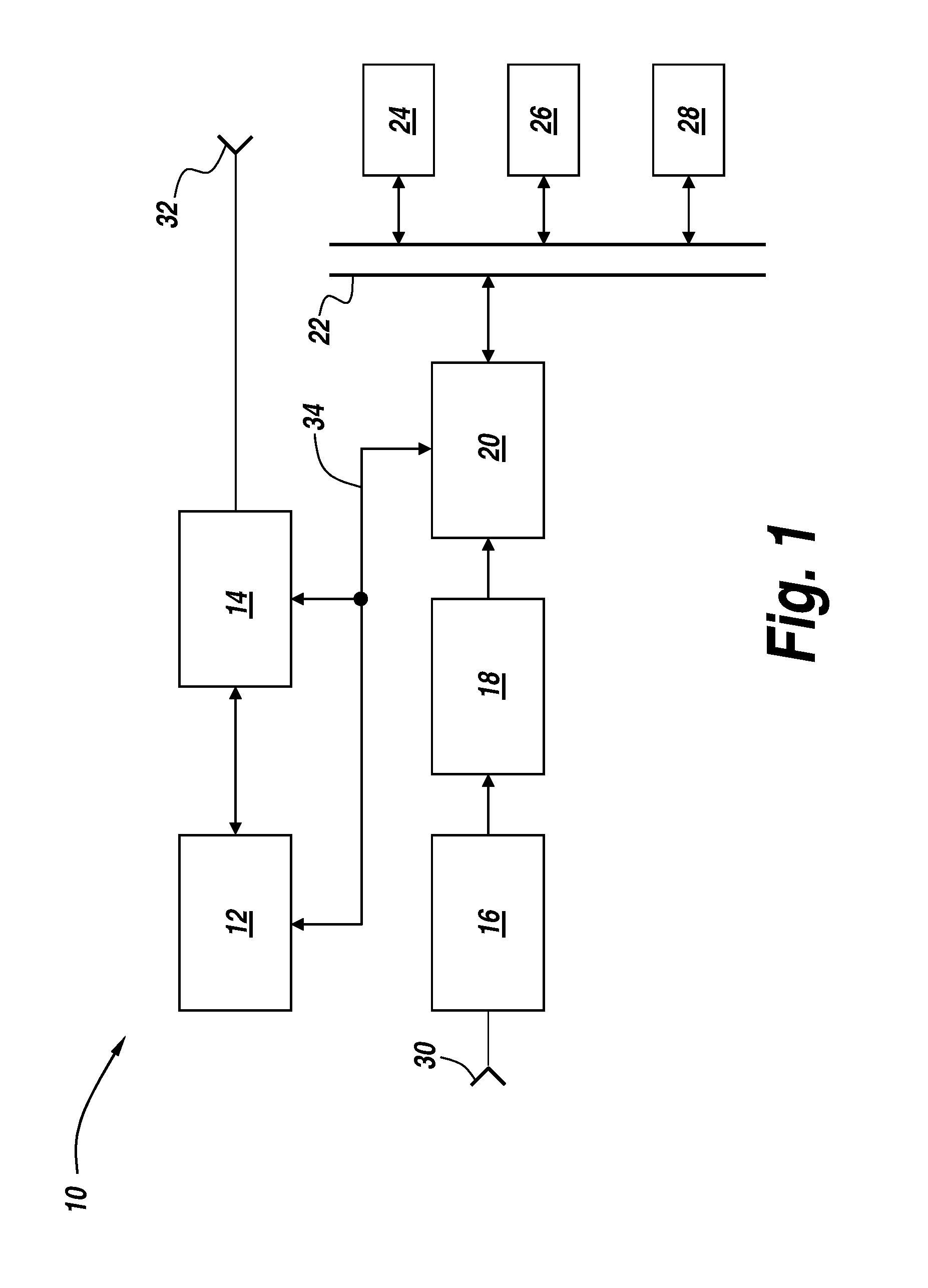
[0032]FIG. 1 includes a schematic block diagram of a radar system 10 for processing radar signals, for example, automobile radar signals, in accordance with some exemplary embodiments. Referring to FIG. 1, radar system 10 generates and transmits radar signals into a region that is being monitored by radar system 10. Generation and transmission of signals is accomplished by RF signal generator 12, radar transmit circuitry 14 and transmit antenna 32. Radar transmit circuitry 14 generally includes any circuitry required to generate the signals transmitted via transmit antenna 32, such as pulse shaping circuitry, transmit trigger circuitry, RF switch circuitry, or any other appropriate transmit circuitry used by radar system 10. RF signal generator 12 and radar transmit circuitry 14 can be controlled via a processor 20 issuing commands and control signals via control lines 34, such that the desired RF signal having the desired configuration and signal parameters is transmitted at transm...


PUM


Abstract

Determining distance and relative speed includes a transmitter transmitting electromagnetic signals defined by a plurality of sections, a first section comprising a continuous-wave (CW) signal, a second section comprising a chirp electromagnetic signal, the chirp electromagnetic signal comprising a plurality of subsections. A detector detects reflected signals being the transmitted electromagnetic signals reflected from an object, and comprising a reflected CW signal and a reflected chirp signal. The detector detects the reflected signals by: (i) generating a plurality of samples of the reflected CW signal, and (ii) generating a plurality of samples of the reflected chirp signal. A processor determines a first set of phase differences among the plurality of samples of the reflected CW signal and a second set of phase differences among the plurality of samples of the reflected chirp signal, and processes the first and second sets of phase differences to determine the distance, relative speed and bearing.

Description

BACKGROUND[0001]1. Technical Field[0002]This disclosure relates to radar systems and methods, and, more particularly, to radar systems and methods using a modified radar signal and signal processing approach to determine relative velocity (Doppler), range and bearing of one or more objects, including simultaneous determination of relative velocity, range and bearing of multiple objects.[0003]2. Discussion of Related Art[0004]In a typical radar system, a transmitter transmits an electromagnetic signal from an observation point, and a receiver located at or near the observation point receives an echo signal, or reflected signal, from an object. The echo signal or reflected signal is the result of the transmitted electromagnetic signal striking the object and being reflected by the object back to the receiver. Processing of the echo or reflected signals can be performed to determine certain parameters related to the remote object, such as, for example, relative distance or radial range...

Claims


Application Information

Patent Timeline
Patent Type & Authority Applications(United States)
IPC IPC(8): G01S13/58G01S13/931
CPCG01S13/58G01S7/354G01S13/32G01S13/345G01S13/42G01S13/536G01S13/584G01S13/931G01S13/347
Inventor HAMPIKIAN, PAUL
Owner ARRIVER SOFTWARE LLC (N D GES D STAATES DELAWARE)
Why Eureka
Try Eureka