Eureka AIR delivers breakthrough ideas for toughest innovation challenges, trusted by R&D personnel around the world.

Inverter-integrated electrically driven compressor

a compressor and inverter technology, applied in the direction of positive displacement liquid engines, pumps, machines/engines, etc., can solve the problems of unintentional touching of high voltage parts and the cover can be removed, so as to reduce the size, ensure the safety, and reduce the cost

Active Publication Date: 2015-11-12
MITSUBISHI HEAVY IND THERMAL SYST
View PDF1 Cites 10 Cited by
  • Summary
  • Abstract
  • Description
  • Claims
  • Application Information

AI Technical Summary

Benefits of technology

The present invention is about a compressor system integrated into an electrified vehicle. The system is designed to be safe without any special safety mechanisms. The connector on the power line side is always connected to the connector on the compressor side, so the power line and other components remain connected to the inverter device. This prevents any danger of contacting the internal inverter device while power is applied. This design ensures safety without any additional measures and reduces the size and cost of the system by eliminating the need for special safety mechanisms or interlocks. The cover of the inverter housing is always securely fastened, making it easy to remove without risking contact with the internal components. In summary, this invention simplifies the design of a safe and reliable electrified vehicle system.

Problems solved by technology

Therefore, there is a danger that the cover can be removed while the power is still applied to the inverter device, and a high voltage part can be unintentionally touched.

Method used


Image

  • Inverter-integrated electrically driven compressor
  • Inverter-integrated electrically driven compressor
  • Inverter-integrated electrically driven compressor

Examples


Embodiment Construction

[0024]The following is a description of an embodiment of the present invention with reference to FIGS. 1 to 4.

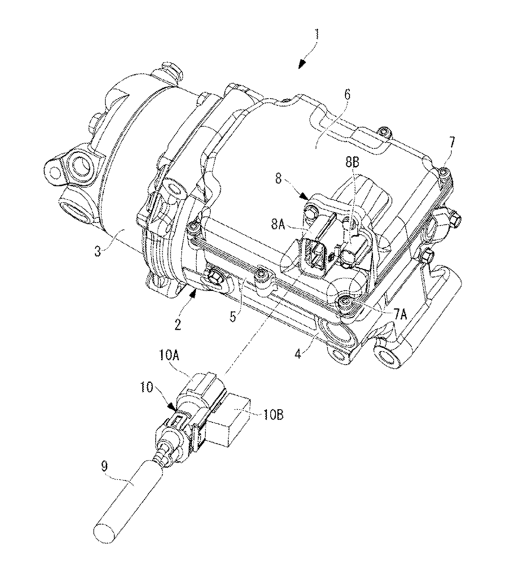
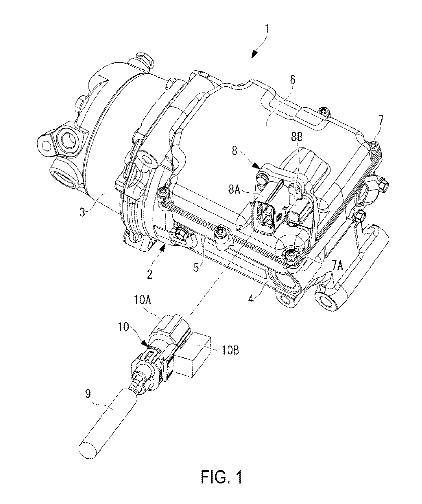
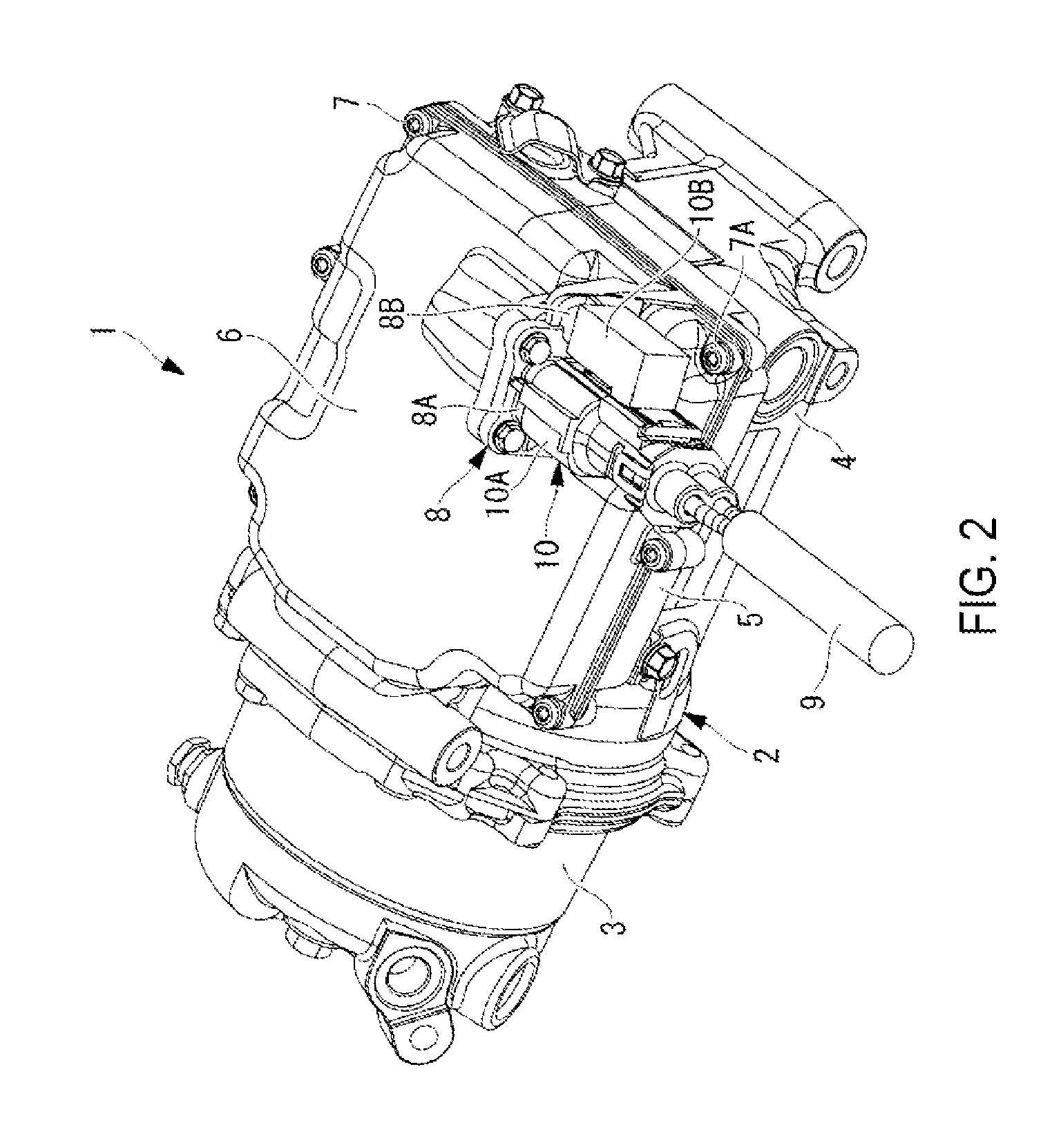
[0025]FIG. 1 is a perspective view of an inverter-integrated electrically driven compressor according to an embodiment of the present invention with a connector on a power line side coupled, and FIG. 2 is a perspective view with the connector on the power line side decoupled.

[0026]An inverter-integrated electrically driven compressor 1 includes a housing 2 that houses therein an electric motor and a compressor driven by the electric motor, which are not illustrated on the drawings. The housing 2 is configured with an aluminum diecast motor housing 3 and compressor housing 4 integrally coupled.

[0027]An inverter housing part 5 is integrally formed on the outer periphery of the motor housing 3 that houses the electric motor in the housing 2. The inverter housing part 5 has a box shape with the top surface open, configured so that an inverter device, which is not illustrated on ...


PUM


Abstract

The purpose is to provide an inverter-integrated electrically driven compressor by which the danger of contacting an inverter device while power is being applied can be overcome in a reliable manner, without the need to provide any extra components, such as safety devices or the like. In this inverter-integrated electrically driven compressor, the inverter device is arranged housed within an inverter housing part hermetically sealed by a cover, and power and communication lines from an external power supply and a control device are connectable to the inverter device through connectors. The connector on the compressor side is furnished to the cover side, and at least one bolt of a fastening means for fastening the cover to the inverter housing part is furnished at location covered by the connector on the power line side, making access impossible, when the connector on the power line side has been coupled to the connector on the compressor side.

Description

TECHNICAL FIELD[0001]The present invention relates to an inverter-integrated electrically driven compressor in which an inverter device is integrally incorporated into an inverter housing part of the housing.BACKGROUND ART[0002]Electric compressors that integrally incorporate an inverter device are used as air conditioner compressors installed in electric vehicles, hybrid vehicles, or the like. In an inverter-integrated electrically driven compressor, an inverter housing part is furnished on the outer periphery of the housing that houses a compressor and an electric motor that drives the compressor, and an inverter device that converts high voltage direct current power supplied from a power supply unit into three-phase alternating current power which is applied to the electric motor is arranged housed within the inverter housing part. Further, the inverter housing part is hermetically sealed by a cover.[0003]The electric compressor for a vehicle air conditioner is normally installed...

Claims


Application Information

Patent Timeline
IPC IPC(8): H02K5/10H02K5/22H02K11/00
CPCH02K5/10H02K11/0073H02K5/225H02K11/0094F04B35/04F04B39/121H02K11/33
Inventor ARASHI, NORIAKI
Owner MITSUBISHI HEAVY IND THERMAL SYST
Why Eureka
Eureka Blog
Learn More