Eureka AIR delivers breakthrough ideas for toughest innovation challenges, trusted by R&D personnel around the world.

Machining system and tool holding apparatus thereof

Active Publication Date: 2015-11-19
GENERAL ELECTRIC CO
View PDF6 Cites 0 Cited by
  • Summary
  • Abstract
  • Description
  • Claims
  • Application Information

AI Technical Summary

Benefits of technology

The present invention provides a machining system for electro machining a workpiece. The system includes a machine tool, a cutting tool, and a tool holding apparatus. The tool holding apparatus holds the cutting tool and has a solution releasing element that provides machining solution to the cutting tool. The solution releasing element has at least two groups of channels that release the machine solution onto adjacent sections of the cutting tool. This results in more efficient and effective machining.

Problems solved by technology

While there have been attempts to embed or integrate electromachining into the machining systems, mechanisms for performing the electromachining are relatively complex.
Furthermore, in conventional machining systems, the use of the machining solution is not very efficient because the machining solution is generally released through only one channel / nozzle without flow rate control.

Method used


Image

  • Machining system and tool holding apparatus thereof
  • Machining system and tool holding apparatus thereof
  • Machining system and tool holding apparatus thereof

Examples


Embodiment Construction

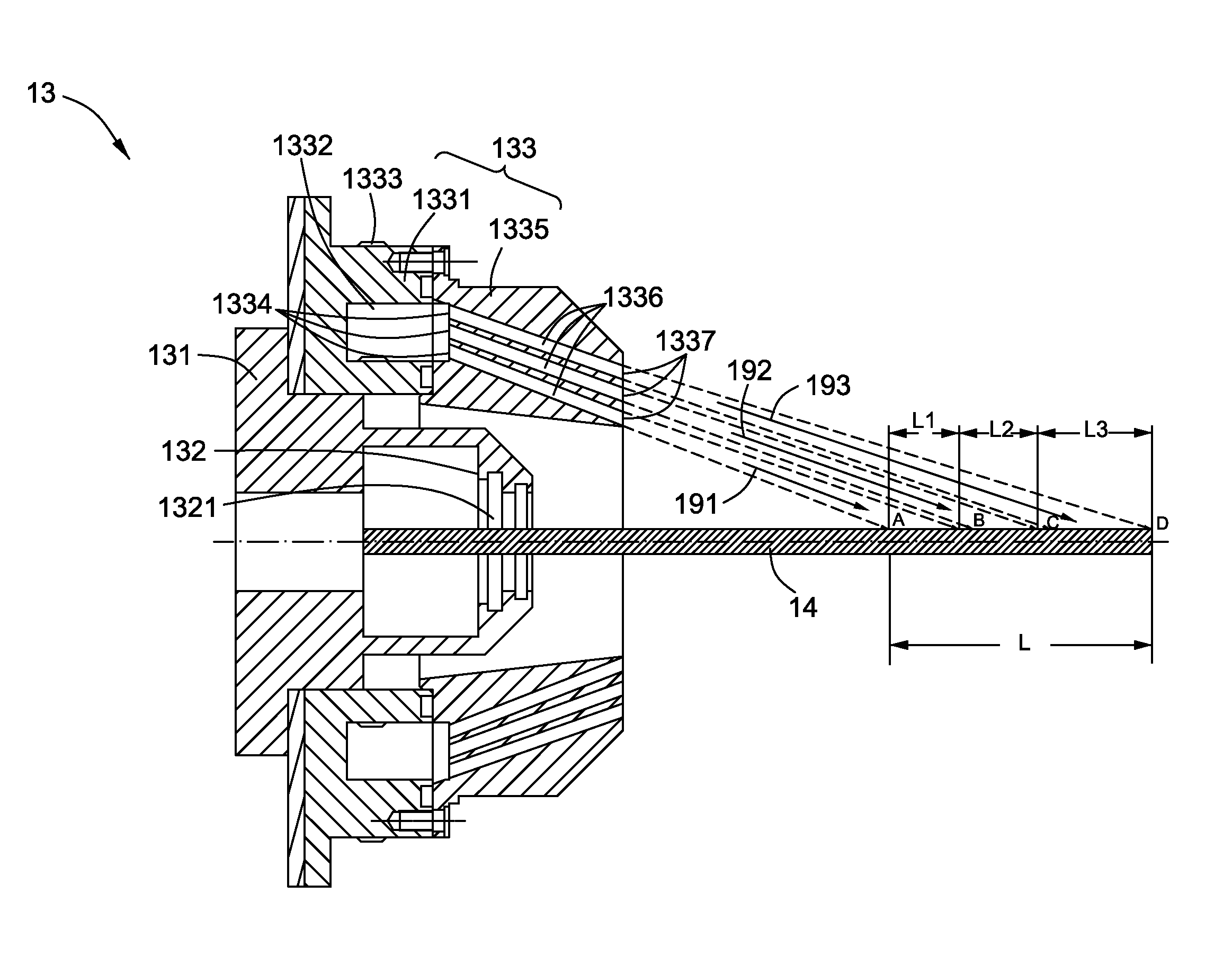
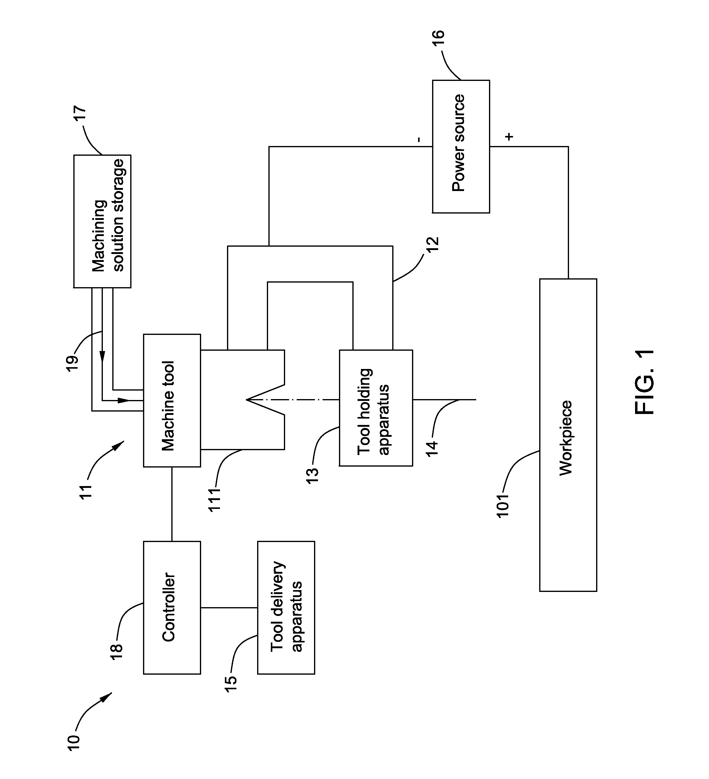
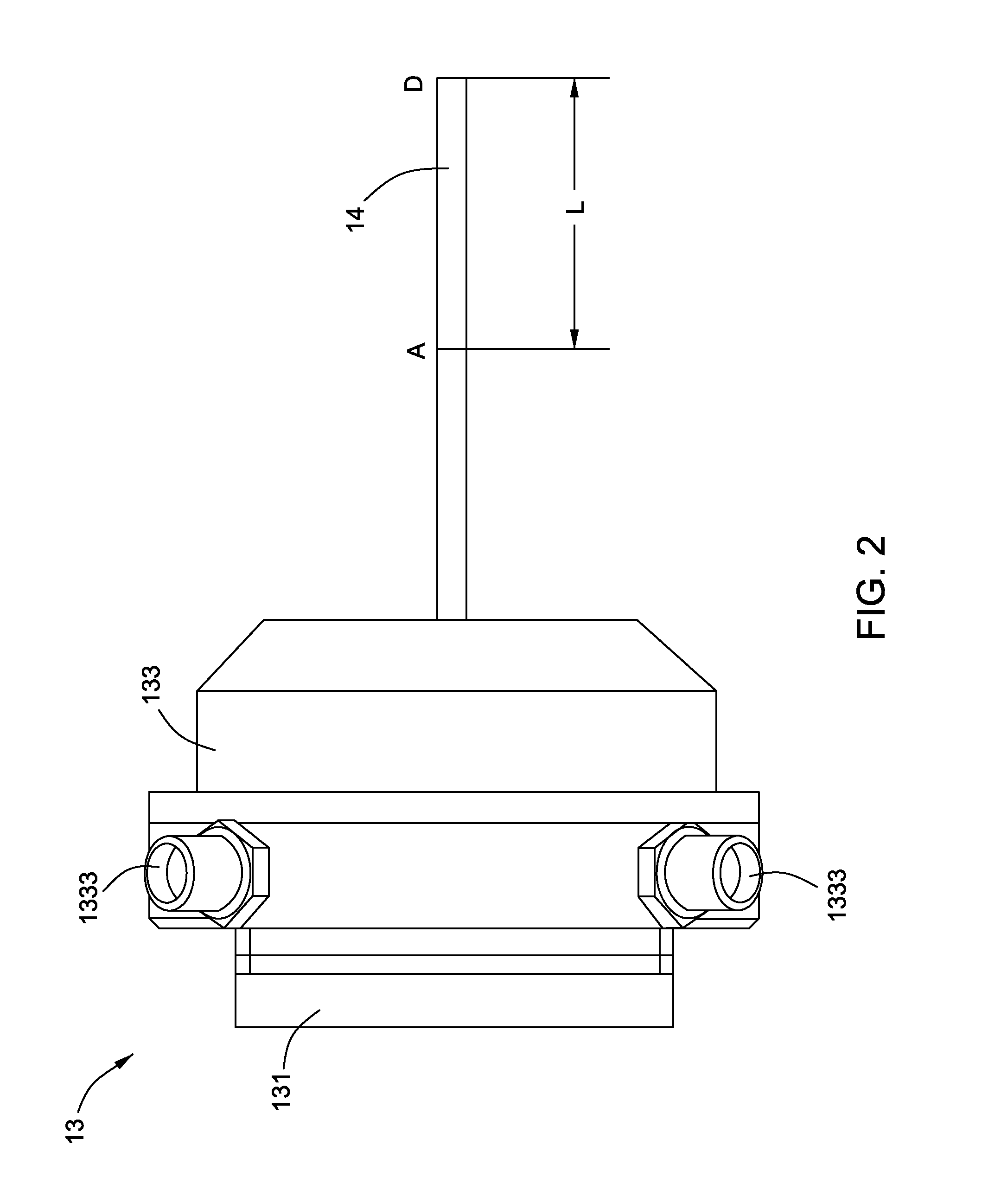
[0017]In the following detailed description, reference is made to the accompanying drawings that form a part hereof, and in which is shown by way of illustration specific embodiments, which may be practiced. These embodiments are described in sufficient detail to enable those skilled in the art to practice the embodiments, and it is to be understood that other embodiments may be utilized and that logical, mechanical, electrical and other changes may be made without departing from the scope of the embodiments. The following detailed description is, therefore, not to be taken in a limiting sense.

[0018]Unless defined otherwise, technical and scientific terms used herein have the same meaning as is commonly understood by one of ordinary skill in the art to which this invention belongs. The terms “first”, “second”, and the like, as used herein do not denote any order, quantity, or importance, but rather are used to distinguish one element from another. Also, the terms “a” and “an” do not...


PUM

PropertyMeasurementUnit
Flow rateaaaaaaaaaa
Areaaaaaaaaaaa
Circumferenceaaaaaaaaaa

Abstract

A machining system for electromachining a workpiece that in one embodiment includes a machine tool, a cutting tool for performing the eletromachining, and a tool holding apparatus for conductively holding the cutting tool and coupled to the machine tool. The tool holding apparatus includes a holding element for holding the cutting tool and at least one solution releasing element. The solution releasing element is used to receive machining solution and release the machining solution onto a predetermined area of the cutting tool through at least one group of channels. Each group of channels includes at least two channels configured to respectively release the machining solution onto at least two adjacent sections in the predetermined area of the cutting tool.

Description

BACKGROUND[0001]This application relates generally to machining systems. More particularly, this application relates to a tool holding apparatus applied on a machining system for electromachining.[0002]Electromachining, such as electro discharge machining (EDM), electrochemical machining (ECM), and electrochemical discharging machining (ECDM) are processes and systems in which an electrode is positioned nearby an electrically conductive workpiece, and an electrical current passes between the electrode and the workpiece to locally process the workpiece to form desired features thereon. A machining solution is released onto the electrode to carry the removed materials away. This noncontact machining has a number of advantages over the contact type machining processes. Typically, the electromachining apparatus has a channel / nozzle that is integrated in a tool holding apparatus that provides for the machining solution to be dispensed. The tool holding apparatus is used to hold the cutti...

Claims


Application Information

Patent Timeline
IPC IPC(8): B23H7/36B23H7/26
CPCB23H7/26B23H7/36B23H1/10B23H7/265B23H9/14B23B2231/24B23H5/02
Inventor YANG, LEILIU, DONGYUAN, RENWEIWU, JIANPINGLUO, YUANFENGWEAVER, HOWARD PAUL
Owner GENERAL ELECTRIC CO
Why Eureka
Eureka Blog
Learn More