Robot system controlling method, program, recording medium, robot system, and diagnosis apparatus

a robot system and robot technology, applied in the field of robot system control, can solve the problems of increased power consumption, work loss, and interference of articulated robots with other objects, and achieve the effect of less errors

Active Publication Date: 2015-11-19
CANON KK
View PDF8 Cites 30 Cited by
  • Summary
  • Abstract
  • Description
  • Claims
  • Application Information

AI Technical Summary

Benefits of technology

[0008]Embodiments of the present invention provide a robot system controlling method capable of estimating a load state of each joint accurately and determ

Problems solved by technology

An articulated robot may interfere with another object in any situations including test operation, teaching, and actual operation.
When an articulated robot interferes with another object, there is a possibility that an overload is caused in a particular joint so that an origin is shifted, or that a damage is caused in a part such as a reduction gear, a bearing, or the like constituting the joint.
If an articulated robot is operated in a state where an origin is shifted in a joint or a part of a joint is damaged, a work may be dropped due to deteriora

Method used


Image

  • Robot system controlling method, program, recording medium, robot system, and diagnosis apparatus
  • Robot system controlling method, program, recording medium, robot system, and diagnosis apparatus
  • Robot system controlling method, program, recording medium, robot system, and diagnosis apparatus

Examples


first embodiment

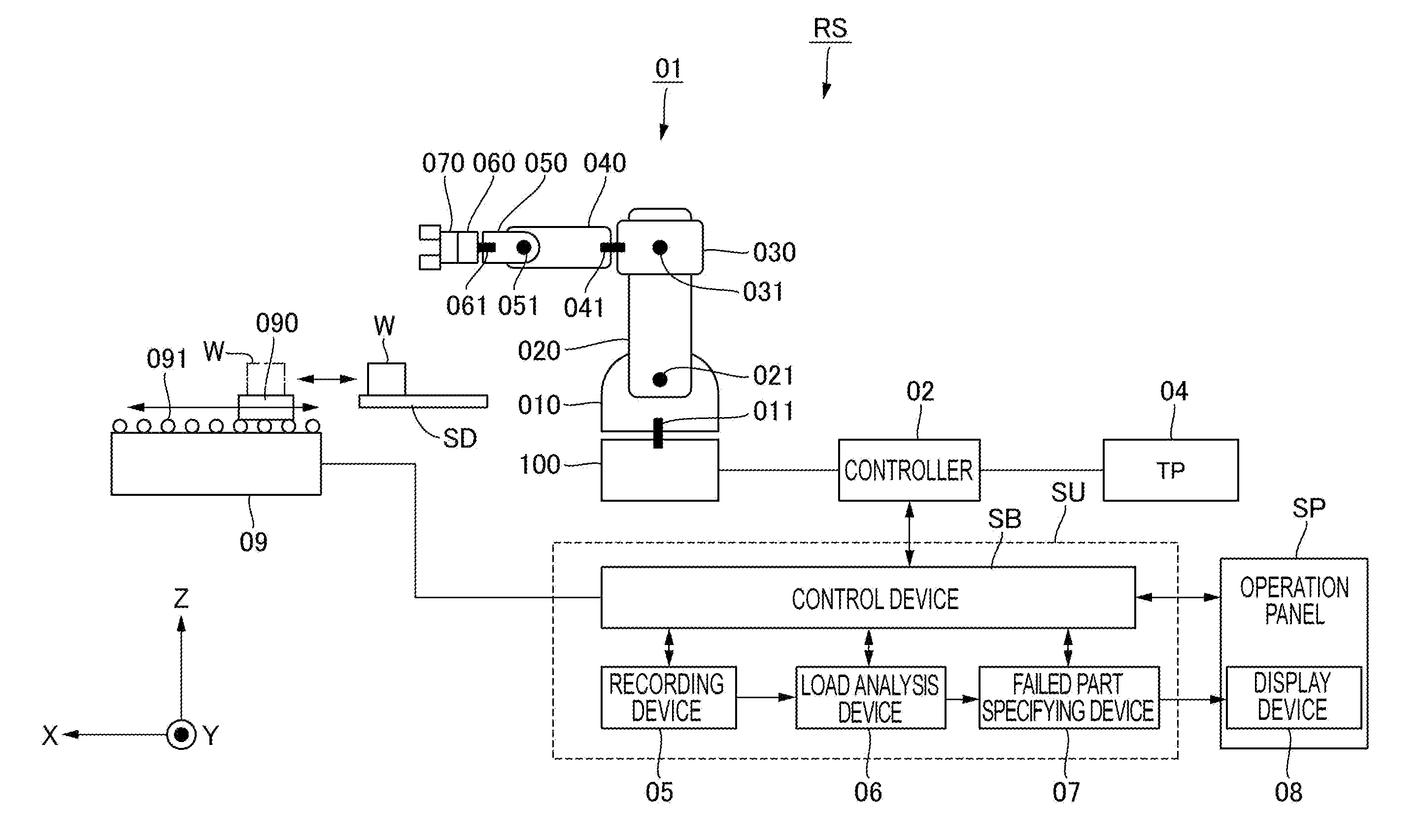
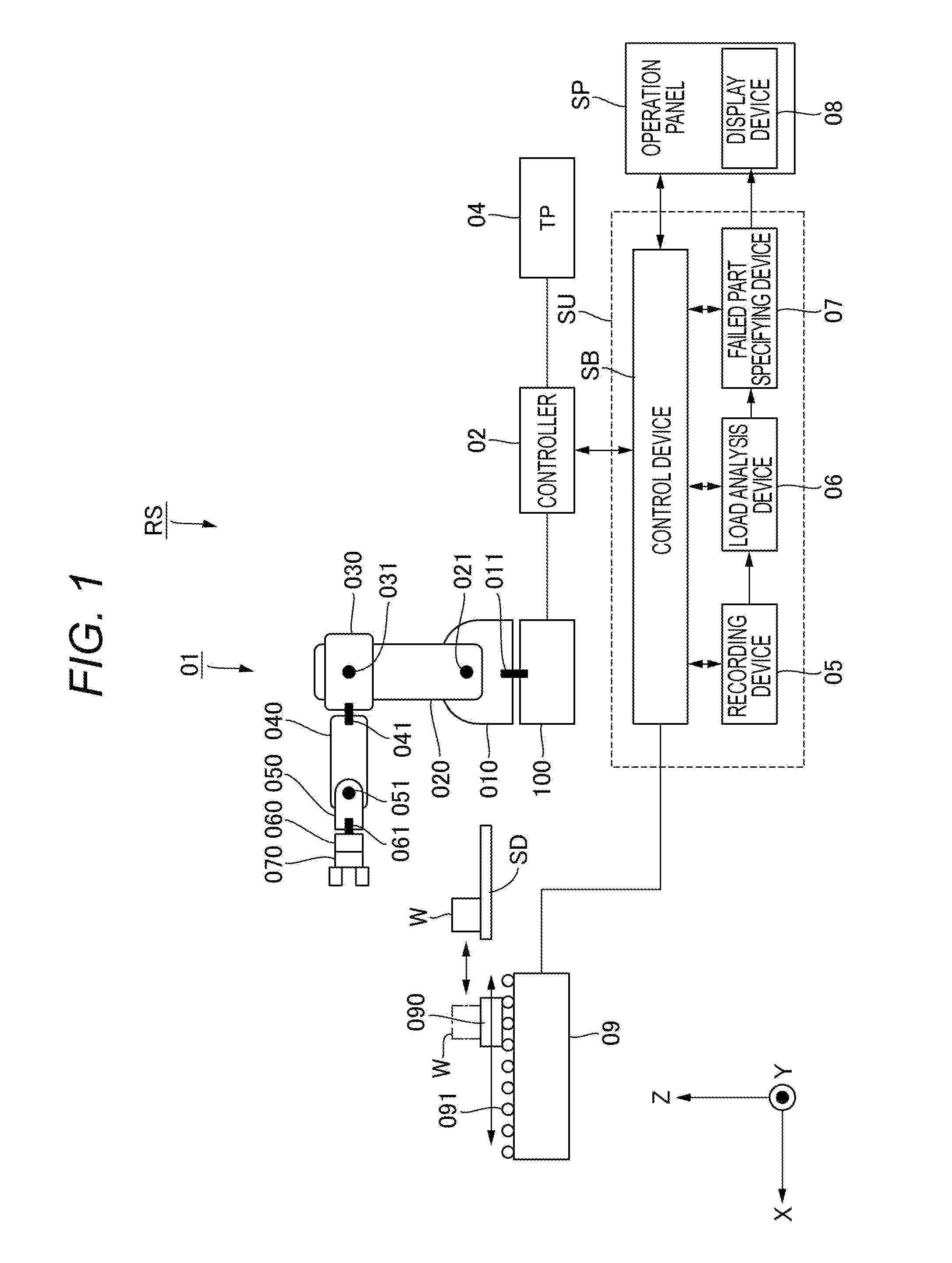
[0036]FIG. 1 is a diagram illustrating an overall configuration of a robot system according to a first embodiment. As illustrated in FIG. 1, in a robot system RS of the first embodiment, when a robot 01 mounted on a production line collides with a device or the like existing around it, a control device SB specifies a failed part of the robot 01. The control device SB specifies which part of which joint of the robot 01 is broken, from the moving speed and the moving direction of each joint of the robot 01 immediately before the collision recorded on a recording device 05.

(Articulated Robot)

[0037]As illustrated in FIG. 1, the robot 01 takes an initial posture. The robot 01 is a six-axis articulated robot having an end effector 070 provided to a link 060 at the leading edge.

[0038]A base 100 and a link 010 of the robot 01 are connected with each other by a torsional joint 011 which rotates about the axis of rotation in a Z axis direction. The torsional joint 011 has a movable range of ±...

second embodiment

[0126]FIG. 8 is a diagram illustrating a configuration of a robot system according to a second embodiment. As illustrated in FIG. 1, in the first embodiment, constituent elements (05, 06, and 07) for performing failure diagnosis for the robot 01 are incorporated in the control unit of the robot system RS. On the other hand, in the second embodiment, the failure diagnosis apparatus (05, 06, and 07) of the robot 01 is provided outside the control device SB of the robot system RS, as illustrated in FIG. 8. The constituent elements other than these and control of the second embodiment are the same as those of the first embodiment. As such, in FIG. 8, the same constituent elements as those of the first embodiment are denoted by the same reference signs as FIG. 1 and overlapping description is omitted.

[0127]As illustrated in FIG. 8, the control unit SU which is an example of a diagnosis apparatus is capable of being connected with the robot system RS, and continuously receives load inform...


PUM


Abstract

A method of controlling a robot system including an articulated robot and a control device is provided. The articulated robot includes links connected by joints, motors configured to drive the joints respectively, and detection devices configured to detect rotation amounts of the joints respectively. The control device controls the motors. The method includes the steps of, by the control device, recording movement information of the joints based on outputs of the detection devices; when detecting an abnormality in the operation of the articulated robot, determining presence or absence of a failure in the articulated robot based on the movement information recorded in at least a period from before detection of the abnormality until detection of the abnormality; and specifying a failure portion of the articulated robot if it is determined that there is a failure in the articulated robot in the step of determining.

Description

BACKGROUND OF THE INVENTION[0001]1. Field of the Invention[0002]The present invention relates to a method of controlling an articulated robot including a plurality of motors which drive joints connecting links respectively, and a plurality of detection devices which detect rotation amounts of the joints connecting the links respectively.[0003]2. Description of the Related Art[0004]An articulated robot, in which both ends of respective links are connected by rotary joints whereby the links are able to perform a bending movement, has been widely used. In the articulated robot, as some of the links have torsional joints which rotate in a torsional direction within a cross-section vertical to a longitudinal direction of the link, the articulated robot is able to perform complicated movement such as six-axis motion or seven-axis motion similar to that of a human arm.[0005]An articulated robot may interfere with another object in any situations including test operation, teaching, and actu...

Claims


Application Information

Patent Timeline
IPC IPC(8): B25J9/16B25J9/02
CPCB25J9/1674Y10S901/02B25J9/02G05B2219/37214G05B2219/39412B25J9/1633B25J9/1676B25J13/088B25J19/06G05B19/425G05B19/427
Inventor YAJIMA, AKIRAOGAWARA, TAKAYUKIASANO, HIDETADA
Owner CANON KK
Why Eureka
Try Eureka