Air compressor with improved rotating device

Active Publication Date: 2015-11-19
CHOU
View PDF2 Cites 13 Cited by
  • Summary
  • Abstract
  • Description
  • Claims
  • Application Information

AI Technical Summary

Benefits of technology

[0005]One object of the present invention is to provide an air compressor with a rotating device pivotally connected to a piston body, the rotating device including a gear body and a counterweight, wherein the counterweight is provided with a central axle corresponding to the center of the gear body and a crankpin placed at a distance from the central axle, so that the gear body and the counterweight rotates about the central axle; the counterweight is horizontally divided into t

Problems solved by technology

However, the motion resistance is great, and thus the perfor

Method used


Image

  • Air compressor with improved rotating device
  • Air compressor with improved rotating device
  • Air compressor with improved rotating device

Examples


first embodiment

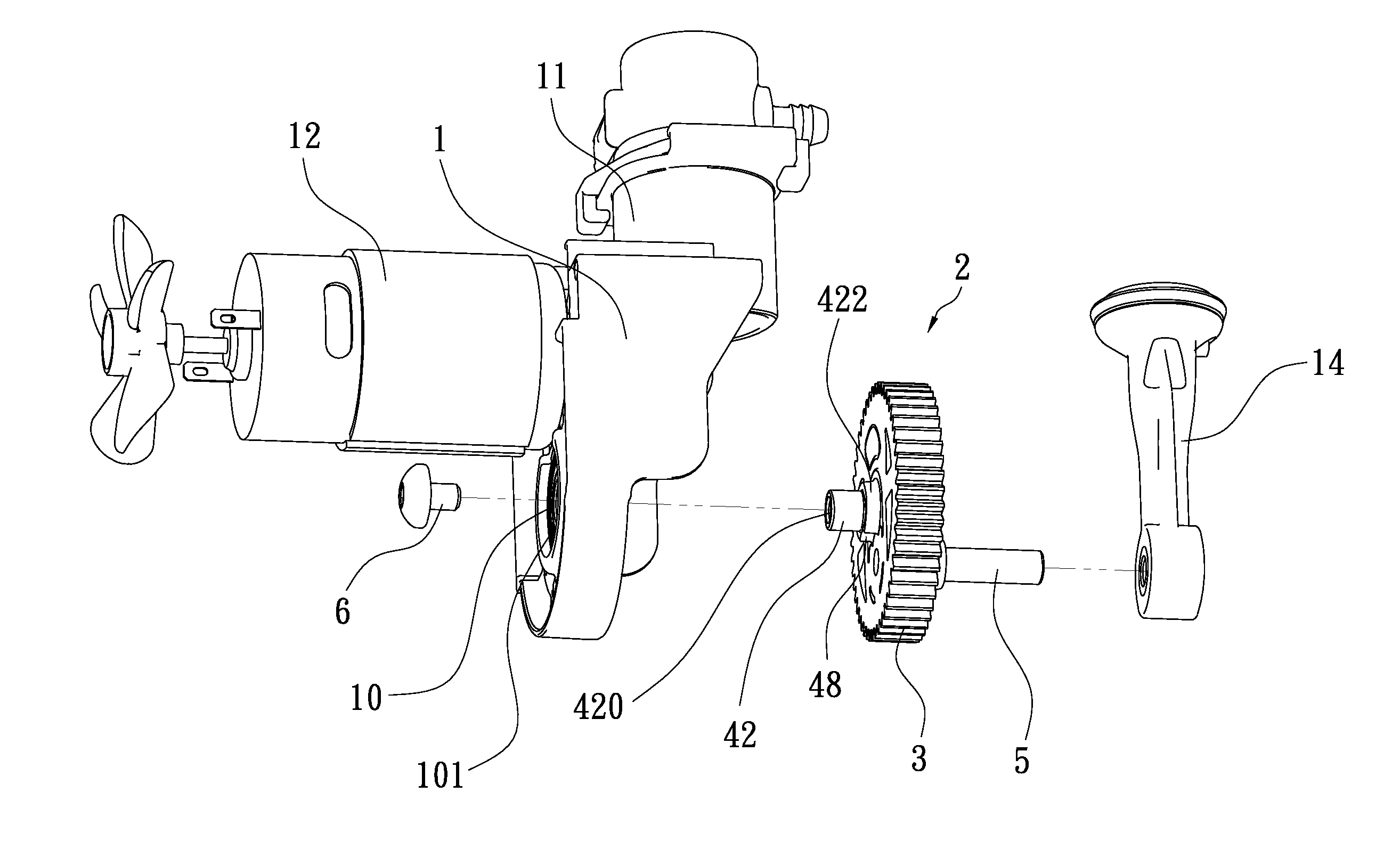
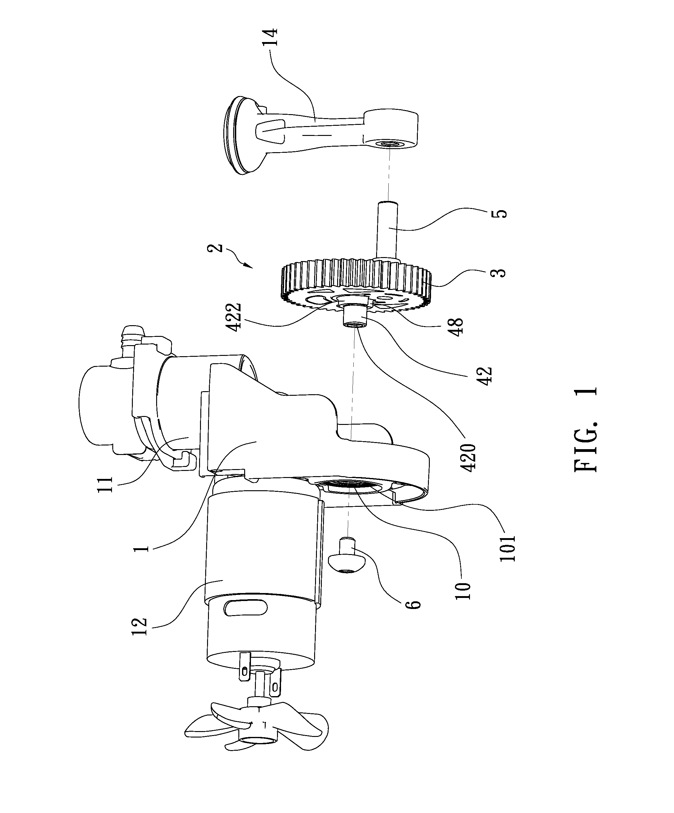
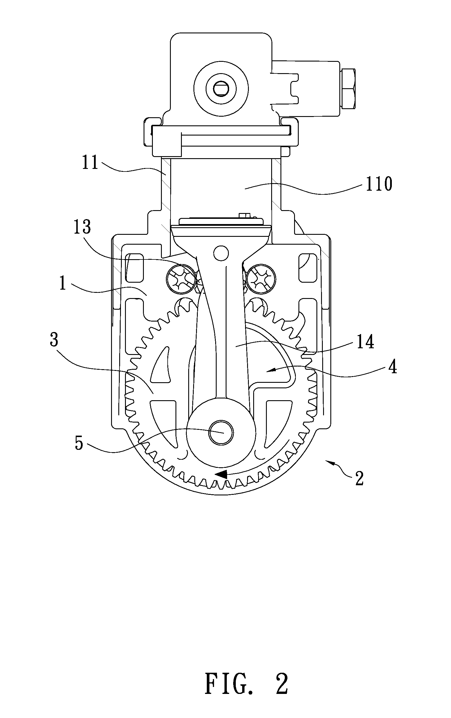
[0018]Referring to FIGS. 1 through 3, an air compressor with a rotating device 2 is shown. The air compressor generally comprises a main frame 1, a cylinder 11 fitted with a piston body 14 and provided at the main frame 1, and a motor 12 mounted to the main frame 1. The motor 12 is fitted with a pinion 13 at its output axle, and the pinion 13 is engaged with the rotating device 2, so that the motor 12 can drive the rotating device 2 to have the piston body 14 conduct reciprocating motion along the inner space 110 of the cylinder 11.

[0019]The rotating device 2 includes a gear body 3 that is assembled with a counterweight 4 provided with a central axle (i.e., crankshaft) 42 corresponding to the center (P1) of the gear body 3 and a crankpin 5 placed at a distance from the central axle 42, the center of crankpin 5 being indicated by (P2) (see FIG. 5). In other words, the central axle 42 is located at the central hub 49 of the rotating device 2, so that the gear body 3 and the counterwei...

second embodiment

[0027]FIGS. 8, 9 and 10 show the rotating device used in the present invention, wherein the rotating device 2 is configured to rotate clockwise, and the counterweight 4 is horizontally divided into two symmetrical halves 411, 412, with a common line (L) connected between the rotational center (P1) of the rotating device 2 and the center (P2) of the crankpin 5; a second recess 44 is defined at the bottom of the lower portion 40, substantially at the right half 412, so that the left half 411 is heavier than the right half 412 (see FIG. 10). Thus, the piston body 14 will gather more rotational momentum from the counterweight 4 at BDC (bottom dead center) to facilitate upstrokes, so that the piston body 14 can conduct reciprocating motion more smoothly and thus the service life of the air compressor can be increased. On the other hand, if the rotating device 2 is configured to rotate counterclockwise, the second recess 44 is substantially defined at the left half 411 of the counterweigh...


PUM


Abstract

An air compressor includes a rotating device pivotally connected to a piston body. The rotating device includes a gear body and a counterweight. The gear body is formed together with a counterweight, wherein the counterweight is provided with a crankshaft corresponding to the center of the gear body and a crankpin placed at a distance from the crankshaft. The counterweight is horizontally divided into two integrally formed halves, including a left half and a right half, with a common line connected between the center of the crankshaft and the center of the crankpin, wherein the first half has a weight different from the second half, so that the piston body gathers more rotational momentum from the counterweight at BDC to facilitate upstrokes, so that the piston body can conduct reciprocating motion more smoothly, and thus the service life of the air compressor can be increased.

Description

(a) TECHNICAL FIELD OF THE INVENTION[0001]The present invention relates to an air compressor and, more particularly, to an air compressor with a rotating device pivotally connected to a piston body, wherein the rotating device includes a gear body and a counterweight, wherein the counterweight is horizontally divided into two integrally formed halves, including a left half and a right half, the first half having a weight different from the second half, so that the piston body will gather more rotational momentum from the counterweight at BDC to facilitate upstrokes, so that the piston body can conduct reciprocating motion more smoothly, and thus the service life of the air compressor can be increased.(b) DESCRIPTION OF THE PRIOR ART[0002]Generally, an air compressor employs a motor to drive a piston to conduct reciprocating motion along the inner space of a cylinder. The air being compressed by the piston can be transferred to an air storage tank. The air storage tank is provided wi...

Claims


Application Information

Patent Timeline
IPC IPC(8): F04B39/00F16C3/30
CPCF04B39/0027Y10T74/2183F16C3/30F04B39/0094F04B39/0022F04B35/04F04B39/122F04B39/14F16F15/262
Inventor CHOU, WEN-SAN
Owner CHOU
Why Eureka
Try Eureka