

Tray apparatus, column with same and method of assembling and using
a tray and column technology, applied in the field of column tray apparatus, can solve the problems of too much momentum and prevent the inlet portion of the downcomer from being used effectively
Inactive Publication Date: 2010-08-10
SULZER MANAGEMENT AG
View PDF34 Cites 1 Cited by
- Summary
- Abstract
- Description
- Claims
- Application Information
AI Technical Summary
Benefits of technology
This solution achieves high flow rates with uniform fluid distribution across the tray, enhancing vapor-liquid contact efficiency and preventing flooding, thereby improving the overall performance of the distillation process.
Problems solved by technology
Method used
View moreImage
Smart ImageViewing Examples

Examples
first embodiment
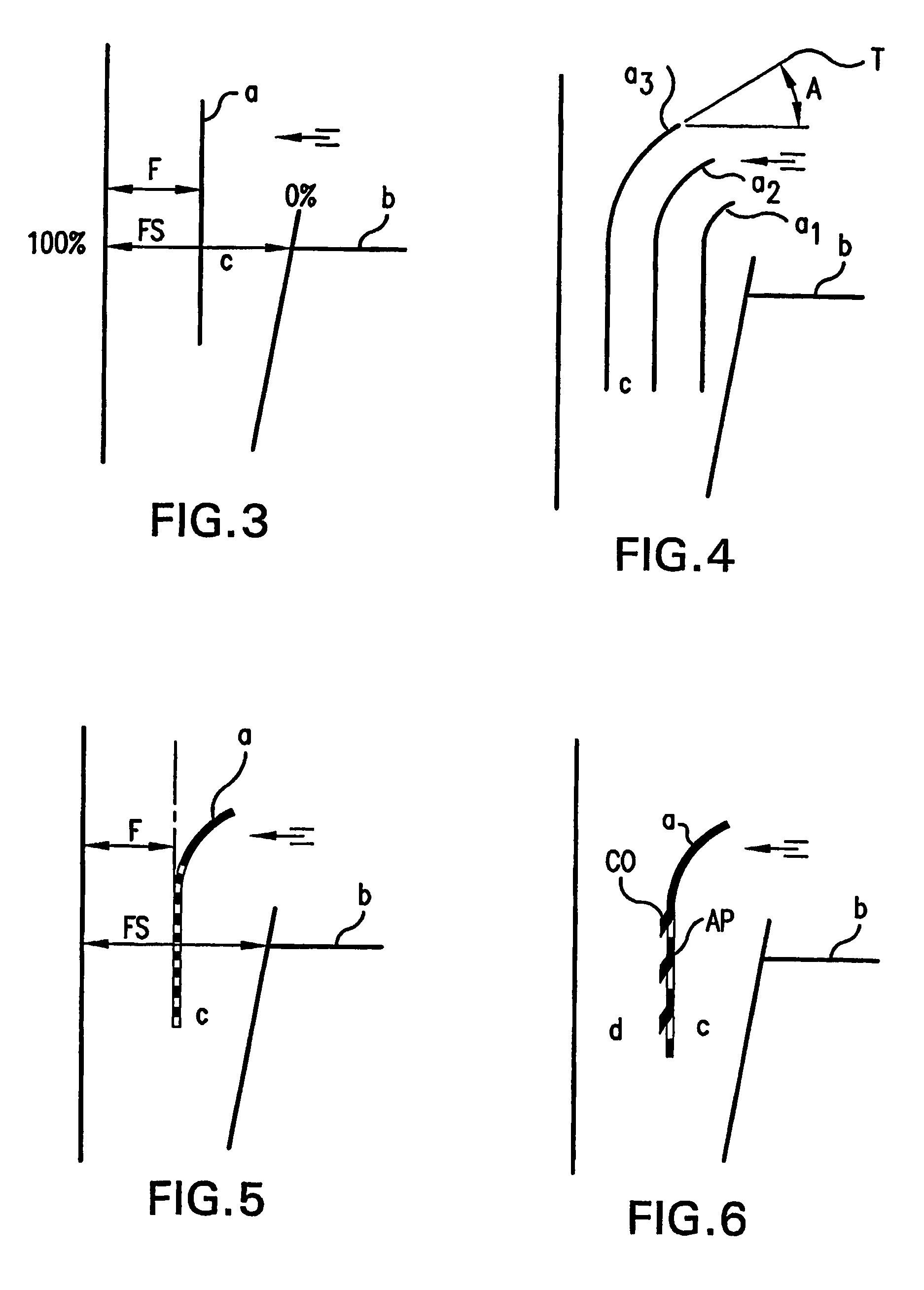
[0036]FIG. 3 shows a planar fluid flow redirecting device extending within an intermediate area of an end downcomer's inlet.
second embodiment
[0037]FIG. 4 shows a fluid flow redirecting device of the present invention with multiple upper end curved, spaced redirecting plates.
third embodiment
[0038]FIG. 5 shows a fluid flow redirecting device of the present invention featuring a top end curved baffle plate with porous vertical, intermediate (boundary curve) and lower plate extension.
Login to View More PUM
 Abstract
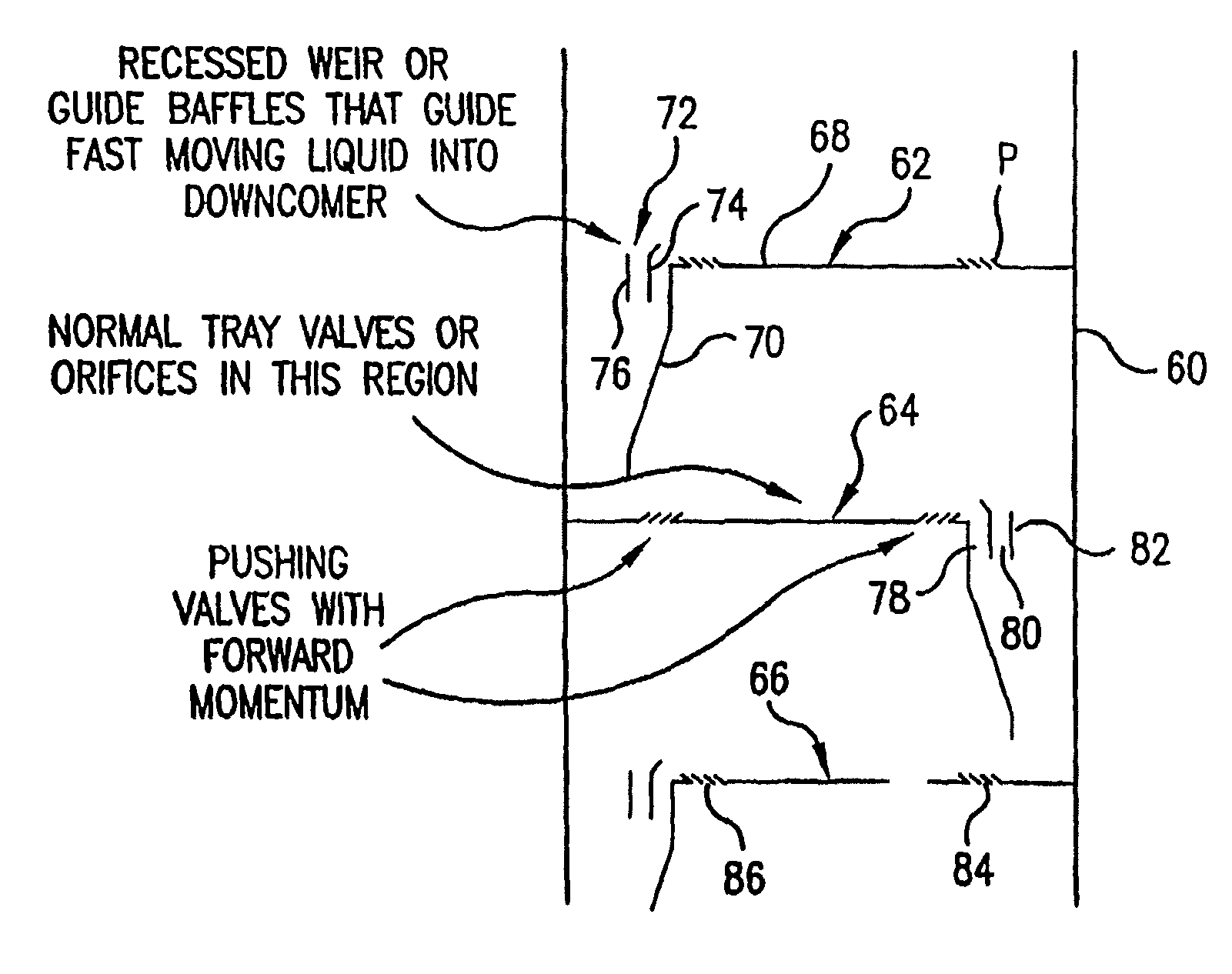
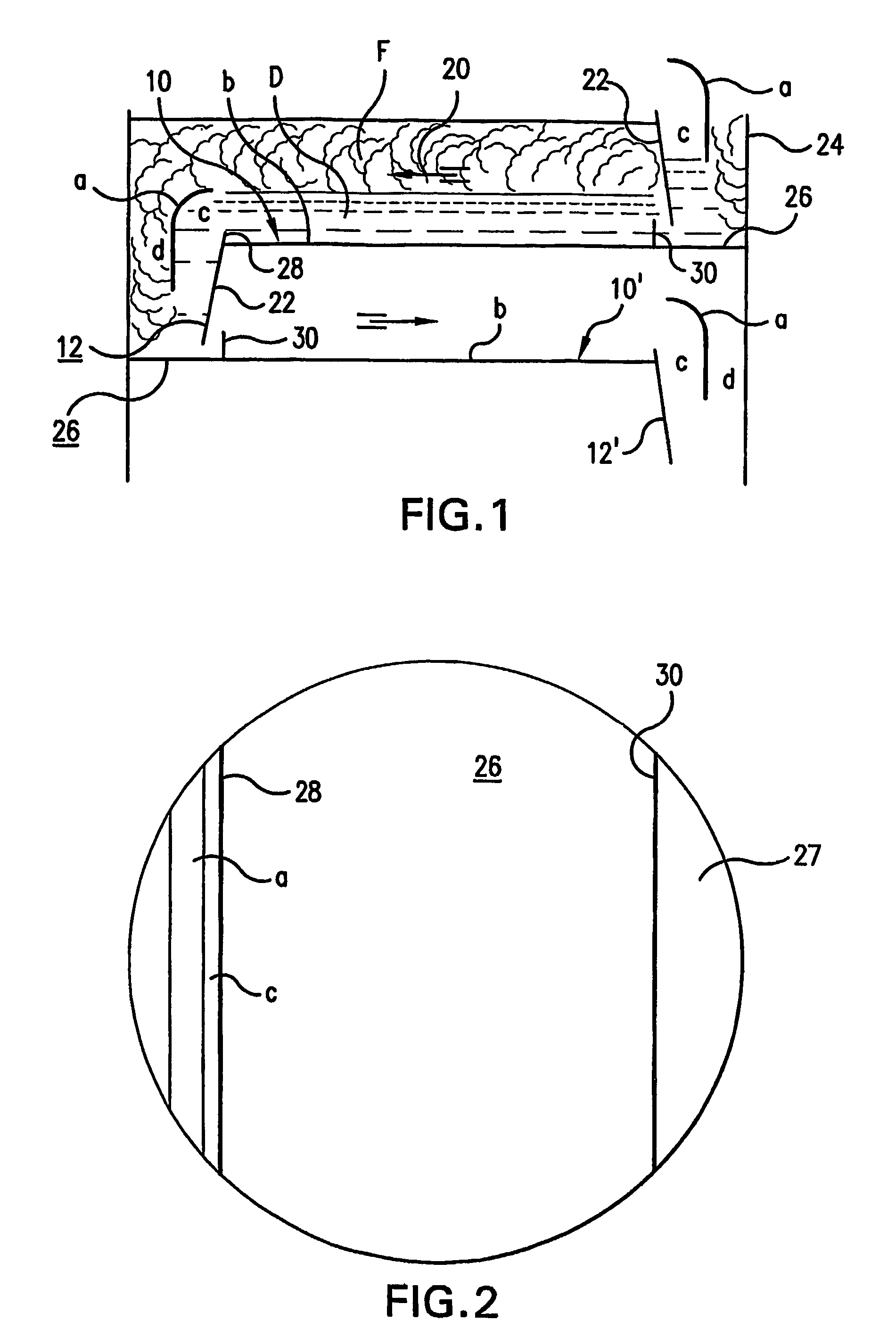
A vapor-liquid contact tray apparatus having a tray with a fluid infeed section and a fluid travel section together with downcomer which is in fluid communication with the fluid travel section of the tray. A redirecting baffle is positioned at an inlet opening of the downcomer and push valves are provided in the fluid travel section of the tray. The push valves are preferably arranged in one or more zones of high concentration of push valves relative to one or more bubbling aperture zones with a lower concentration of push valves or no push valves. The redirecting baffle is provided in the downcomer and extends above the tray to capture fluid flowing horizontally off of the tray (e.g., exiting from a weirless or weir interface) and into a preferably concave upper portion of the redirecting baffle for controlling and redirecting the high momentum flow into and through the downcomer. A plurality of redirecting baffles are featured in one embodiment together with apertured straight sections extending down into the downcomer as in down to the half way mark of downcomer depth or further down including out of the bottom of the downcomer.
Description
PRIORITY[0001]The present invention claims priority under 35 USC §119(e) to U.S. Provisional Patent Application 60 / 445,253 filed Feb. 6, 2003, which application in incorporated herein by reference.FIELD OF THE INVENTION[0002]The present invention is directed at a column tray apparatus such as used in a distillation column, with a preferred embodiment featuring a downcomer and tray with push valves or flow momentum enhancing means combined with flow redirecting means, as in one or more recessed weirs or shaped downcomer inlet guide vanes, for receiving the fluid (e.g., vapor-liquid contact froth) with enhanced momentum and redirecting and discharging the fluid through the downcomer. This invention further relates to mass transfer and exchange columns and, to vapor-liquid contact trays employed within such columns. The invention is also directed at contact trays and methods of assembling and using column tray apparatus and columns with said tray apparatus.BACKGROUND[0003]Vapor-liquid ...
Claims
Login to View More Application Information
Patent Timeline
 Patent Type & AuthorityPatents(United States)
IPC IPC(8): B01F3/04B01D3/20B01D3/22
CPCB01D3/20B01D3/22
InventorPILLING, MARK W.FISCHER, MARKUSMOSCA, GIUSEPPETACCHINI, ELENA
OwnerSULZER MANAGEMENT AG