System, method and apparatus for fluidic effectors for enhanced fluid flow mixing

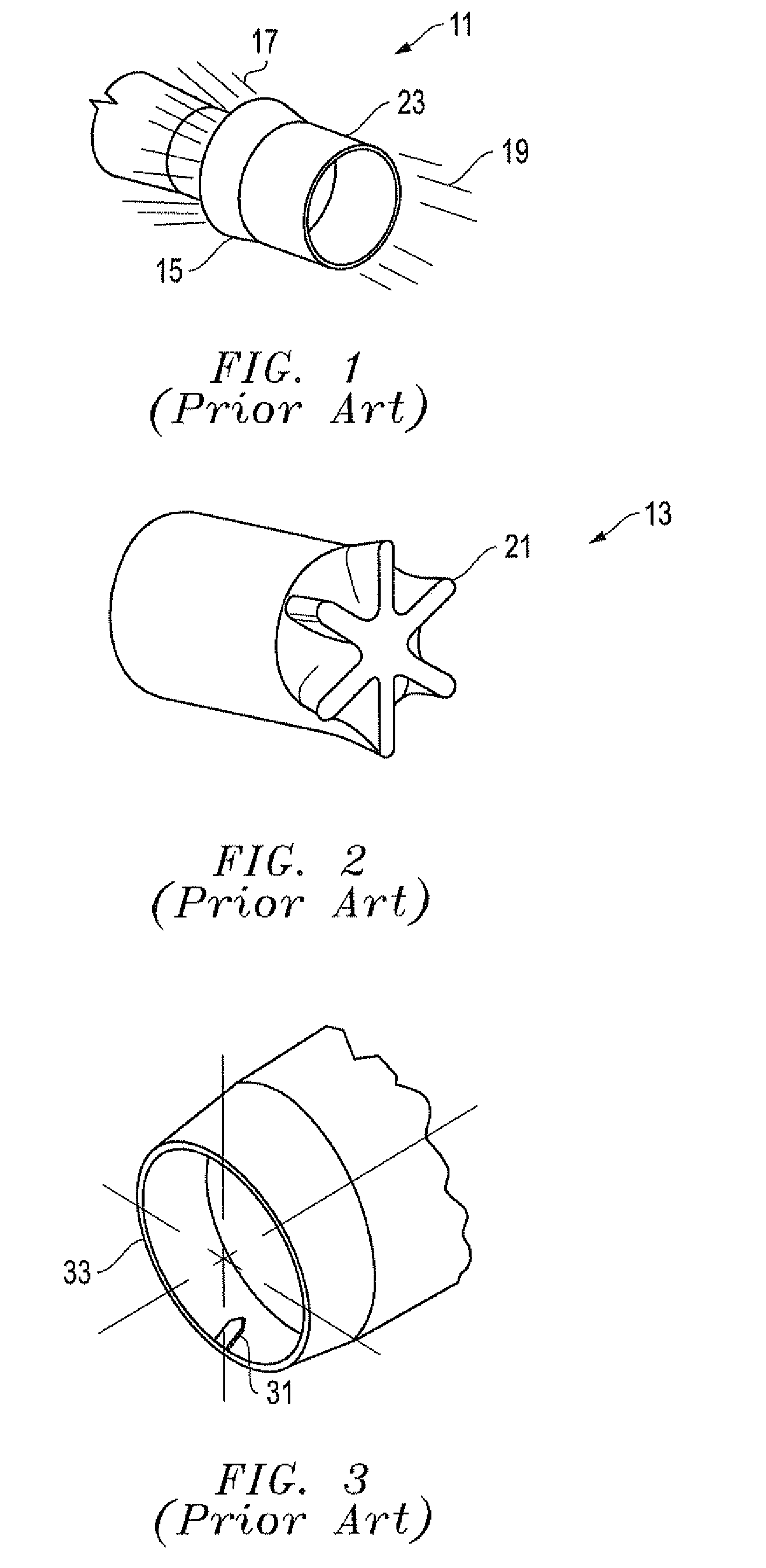
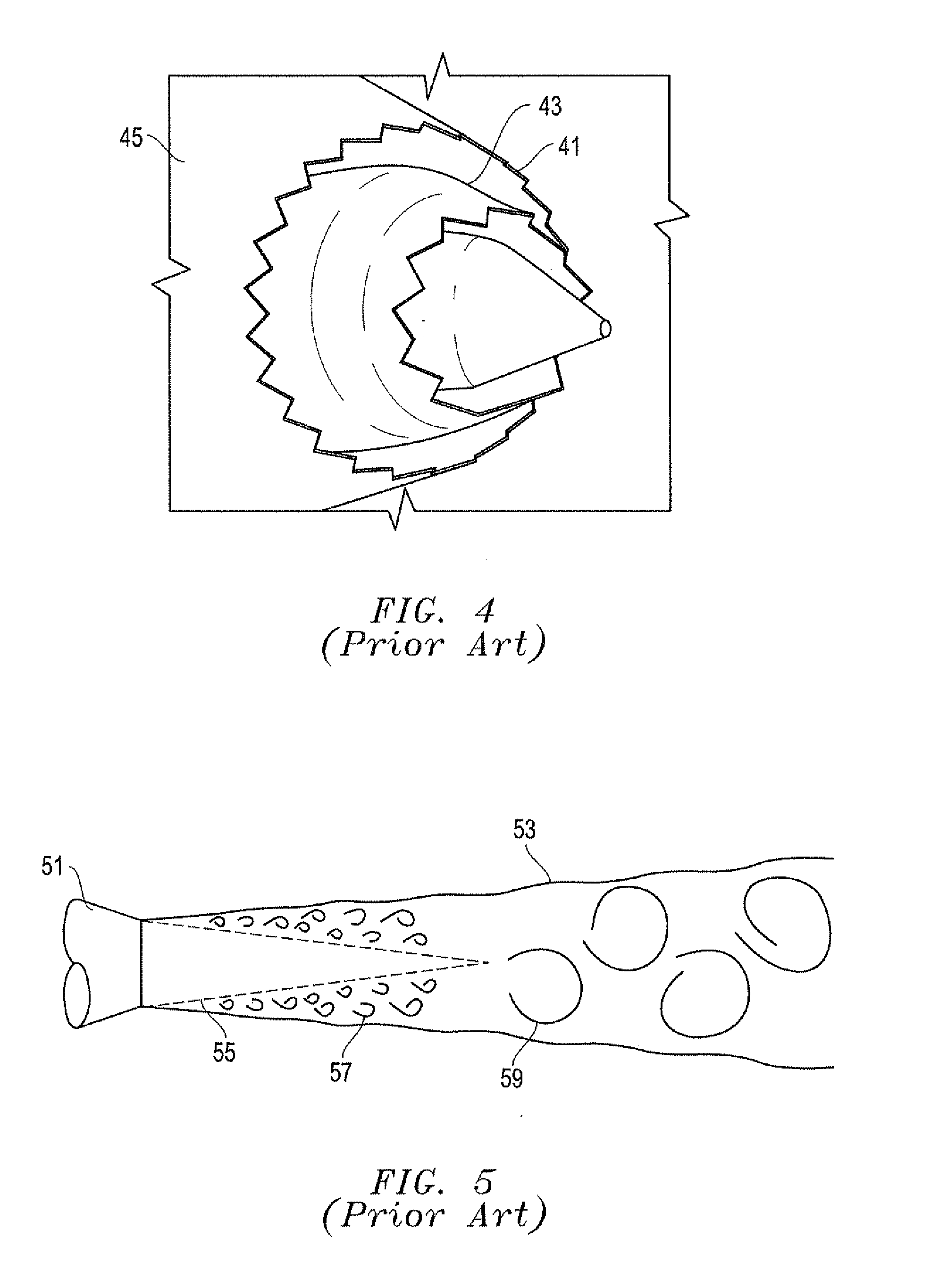
a technology of fluid flow and effector, applied in the system field, can solve the problems of reducing the durability of the nozzle material, significant amount of jet noise, nozzles are typically heavy, bulky and complex, etc., and achieves the effect of enhancing the plume mixing, lowering the noise of the jet and the temperature of the jet exhaus

Active Publication Date: 2009-12-24
LOCKHEED MARTIN CORP
View PDF35 Cites 4 Cited by
  • Summary
  • Abstract
  • Description
  • Claims
  • Application Information

AI Technical Summary

Benefits of technology

[0009]Embodiments of a system, method and apparatus for fluidic effectors that provide enhanced plume mixing. The invention may comprise a fluidic effector having one or more rows of angled air jet injectors on both the external and internal nozzle / cowl surfaces. With the injectors angled in opposite directions, large scale vortices are induced and sustained. These vortices mix actuation air with the exhaust plume to produce ejector action. The plume mixes out quickly, thereby lowering jet noise and jet exhaust temperature.
[0011]Instead of mechanical actuation (e.g., tabs, lobes, etc.), embodiments of the invention use fluidic injectors that can be positioned in the hot gas stream to mix the actuation and exhaust air flows. For example, synthetic, engine compressor-bleed or engine fan-bypass air flow may be provided to the fluidic injectors. The invention increases the shear magnitude between the two fluid streams, and forces greater rotation (i.e., vorticity) and increases penetration of the streams into each other than can be achieved with conventional designs.
[0012]The stream-wise vortices generated have more momentum (i.e., an increased mixing rate) and are able to penetrate further into the exhaust plume since more surface area is available for mixing to occur. The mixing also persists longer because of the increased surface area, resulting in the generation of a uniform velocity aft of the nozzle faster and more affordably than with traditional methods.
[0013]The jet arrays may be tailored with respect to orientation and injection rate, or adjusted to allow variable mixing rates for use at different flight and engine conditions. For example, the system may be adjusted for aircraft take-off low level approach or cruise at altitude. The fluidic ejector system may be turned on and off as needed, so the performance penalties are not carried at all flight conditions. In contrast to the heavy, bulky and complex conventional ejector nozzles, this design is simpler and much lighter in weight. The acoustic and thermal reduction benefits are attractive for non-aviation applications as well, such as other gas turbine applications like power generation and industrial applications involving high pressure fluids.

Problems solved by technology

The high temperature of the exhaust plume reduces the durability of the nozzle material, and the high velocity produces a significant amount of jet noise.
This type of nozzle is typically heavy, bulky and complex, and inherently reduces performance of the engine.
As a result, this solution requires a heavier and more expensive configuration to handle the thermal environment.
This design also has an associated thrust-loss penalty at the nozzle (i.e., internal) and a drag penalty (i.e., externally) because of the increase in size requirements.
This design produces many small vortex pairs and has an associated thrust-loss penalty as the exit flow is impeded.
Moreover, this solution has limited applicability due to the extreme thermal environment inflicted on the tabs 21.
Depending on the application and by-pass ratio (BPR), this design imparts weight penalties and constant drag.
In addition, this solution generates the least beneficial stream-wise vorticity of these conventional designs.

Method used


Image

  • System, method and apparatus for fluidic effectors for enhanced fluid flow mixing
  • System, method and apparatus for fluidic effectors for enhanced fluid flow mixing
  • System, method and apparatus for fluidic effectors for enhanced fluid flow mixing

Examples


Embodiment Construction

[0025]Referring to FIGS. 6-10, embodiments of a system, method and apparatus for fluidic effectors that provide enhanced plume mixing are disclosed. In one embodiment, the invention may be used in an aircraft 61 (FIG. 6) having an engine exhaust system 63. The invention is well suited for abating noise and reducing the exhaust temperature during the emission of the high pressures, velocities and temperatures of the fluids from the engine exhaust system. Although the invention is depicted in use with round engine exhaust nozzles in FIGS. 6 and 7, other shapes such as elliptical and trapezoidal nozzles (see FIGS. 9 and 10) are also suitable for use with the invention.

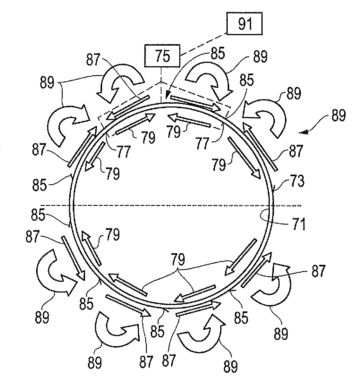
[0026]As shown in FIGS. 7 and 8, the engine exhaust system 63 has a nozzle or aperture 81 (FIG. 8) with an inner surface 71 and an outer surface 73. Depending on the application, the aperture may comprise the engine exhaust nozzle exit lip which is located aft of the nozzle throat 83 and any other location near areas wher...


PUM


Abstract

A fluidic effector provides enhanced plume mixing for an aircraft engine. Air jet injectors are located on both the external and internal cowl surfaces and angled in opposite directions to induce large scale vortices in the exhaust plume. The vortices mix actuation air with the exhaust plume to produce ejector action. The plume mixes out quickly, thereby lowering jet noise and jet exhaust temperature. The injectors have orientations and injection rates that are adjustable to allow variable mixing rates for use at different flight and engine conditions.

Description

BACKGROUND OF THE INVENTION[0001]1. Technical Field[0002]The present invention relates in general to abating noise during the release of high pressure fluids and, in particular, to an improved system, method and apparatus for fluidic effectors that provide enhanced exhaust plume mixing for jet engines.[0003]2. Description of the Related Art[0004]A nozzle exhaust has high temperature and high velocity. The high temperature of the exhaust plume reduces the durability of the nozzle material, and the high velocity produces a significant amount of jet noise. As shown in FIG. 5, a conventional nozzle 51 produces an exhaust plume 53 having a core 55. Small-scale eddies 57 produce high frequency noise downstream from nozzle 51, and large-scale eddies 59 produce low frequency noise further downstream from nozzle 51.[0005]A common way to reduce the exhaust plume temperature and the jet noise is to use an ejector nozzle. Ejector nozzles mix ambient air with the nozzle exhaust. This type of noz...

Claims


Application Information

Patent Timeline
Patent Type & Authority Applications(United States)
IPC IPC(8): B64C23/00F02K1/00F01N1/00
CPCB64D33/06F02K1/46F02K1/34
Inventor LELAND, BRADLEY C.WELLS, DAVID M.
Owner LOCKHEED MARTIN CORP
Why Eureka
Try Eureka