
Radar apparatus with quiet switch calibration and associated methods

a technology of quiet switch and calibration method, which is applied in the field of radar systems, can solve the problems of limiting the range of frequencies allowed and limiting the frequency high that can be effectively generated by beat notes

Active Publication Date: 2015-11-19
DELTA MOBILE SYST
View PDF1 Cites 11 Cited by
  • Summary
  • Abstract
  • Description
  • Claims
  • Application Information

AI Technical Summary

Benefits of technology

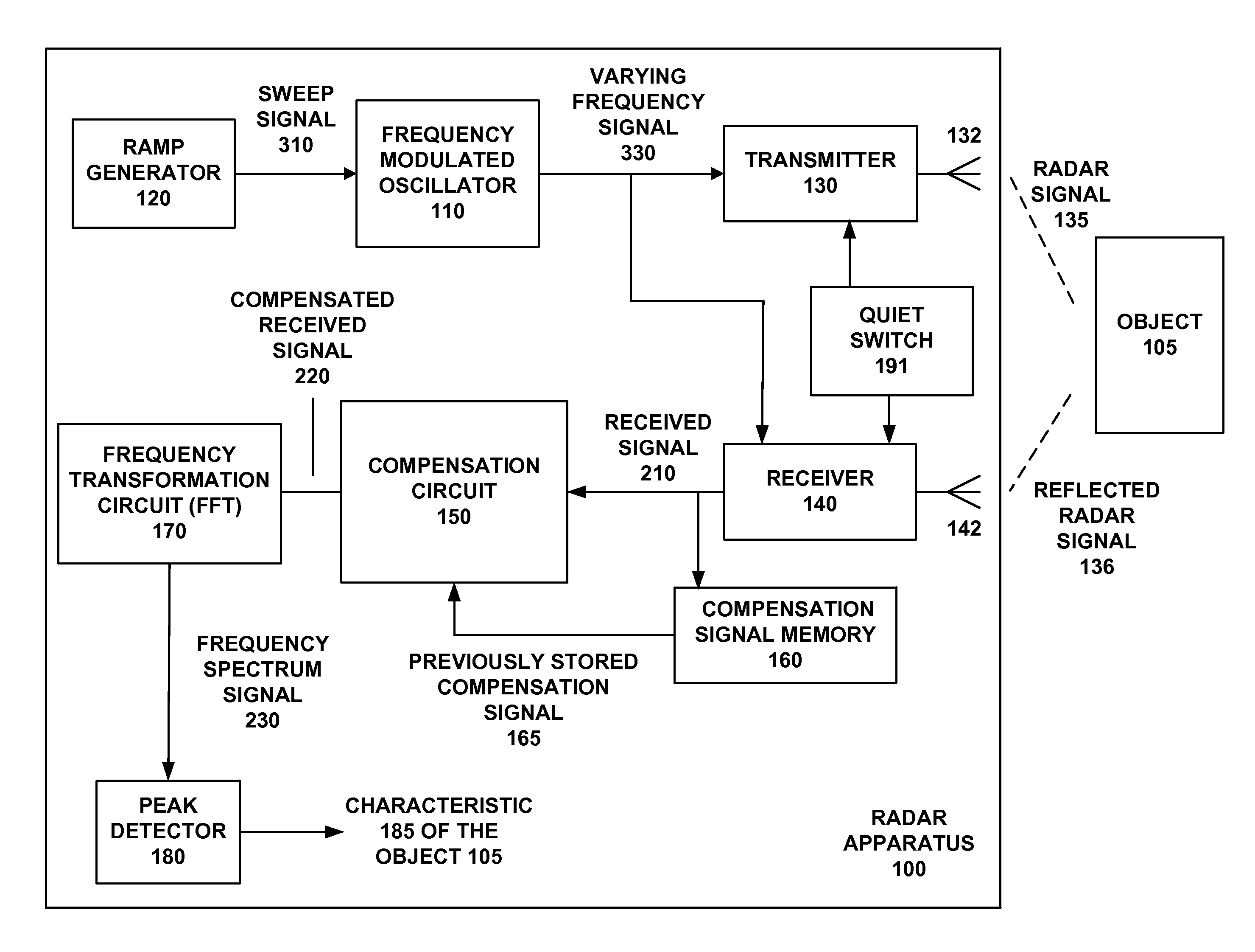
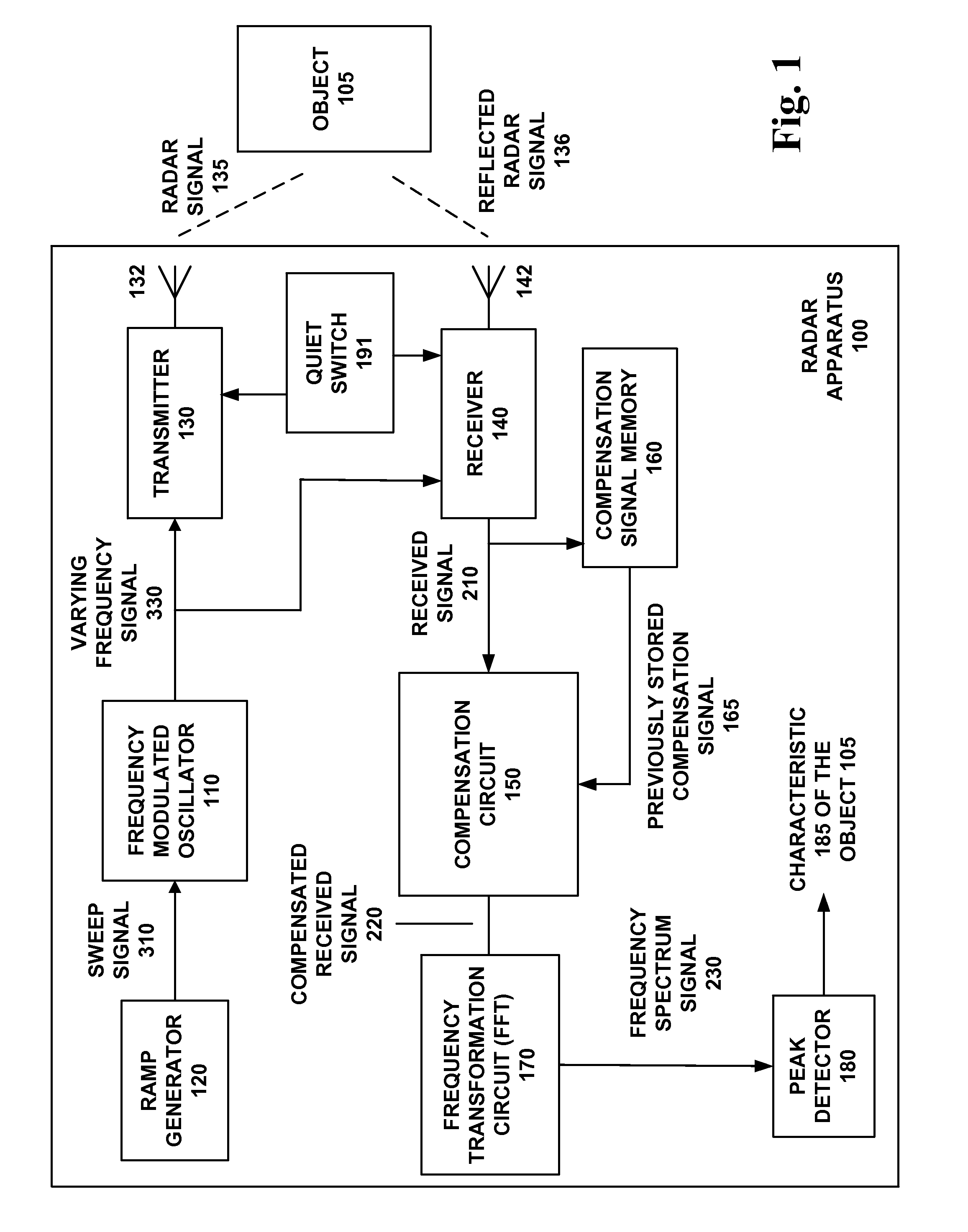
The present invention relates to radar systems that use calibration to improve accuracy in detecting and measuring objects. More specifically, the invention relates to calibrated radar systems that can measure the characteristics of detected objects with a high degree of accuracy, even in the near field. The invention addresses the limitations of traditional FMCW radar systems by using a quiet switch calibration to improve the detection and measurement of targets. The technical effects of the invention include improved accuracy in radar systems, especially in near field applications, and the ability to calibrate radar systems for better detection and measurement of targets.

Problems solved by technology

For typical open-air applications (such as vehicle collision avoidance, presence detection for security or lighting control, and automatic door opening), the FCC limits the range of frequencies allowed.
This band limit, in turn, limits how high in frequency a beat note can be effectively generated for a target at a given range.
Near field determinations of distance ranging and speed determination have been attempted and suffer from inaccuracies the shorter the near field.

Method used


Image

  • Radar apparatus with quiet switch calibration and associated methods
  • Radar apparatus with quiet switch calibration and associated methods
  • Radar apparatus with quiet switch calibration and associated methods

Examples


Embodiment Construction

[0035]For near field targets, because the beat note frequency is low enough to be masked by other factors, distance measurement techniques for traditional radar sensing systems using Frequency Modulated Continuous Wave (FMCW) are inaccurate.

[0036]One of the main factors confounding the detection of near-field objects is the frequency modulation of the carrier signal. This modulation introduces its own signal at a frequency similar to that of the beat note, making it difficult to distinguish the actual beat note with the traditional Fast Fourier Transform (FFT) algorithm. Another confounding factor is leakage and other artifacts generated by the radar unit itself.

[0037]The accuracy of distance measurements are traditionally improved by sweeping a wide bandwidth of the operating frequency of the radar sensing system, e.g. 600 MHz to 1 GHz bandwidth. This method can be utilized by enclosed environments but cannot be used for open air systems due to the above mentioned regulatory restri...


PUM


Abstract

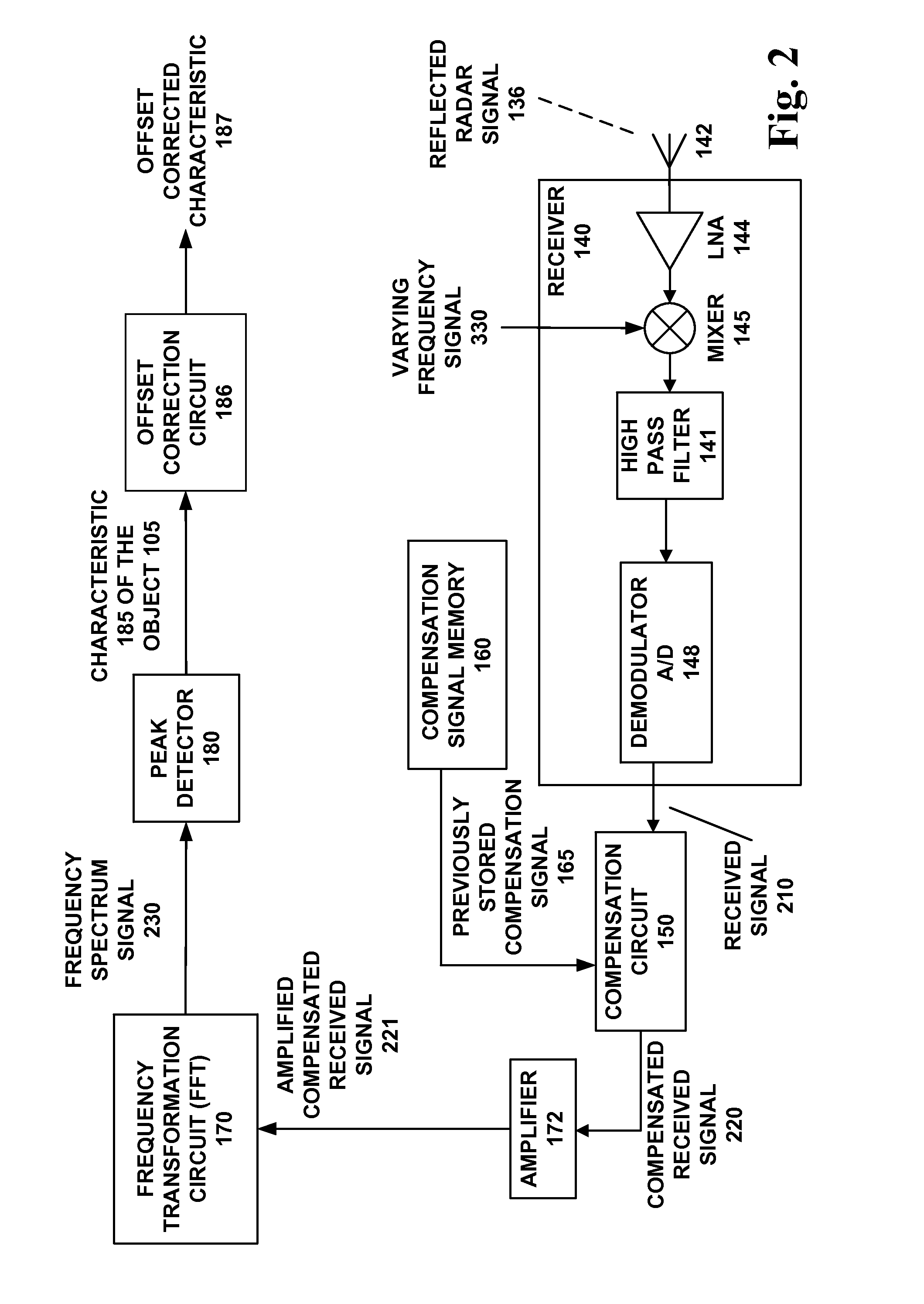
A radar apparatus measures at least one characteristic of at least one object. A sweep generator generates a sweep signal to modulate an oscillator to generate a varying frequency signal. A transmitter transmits the varying frequency signal as a radar signal. A receiver receives a reflected radar signal to produce a received signal using the varying frequency signal. A compensation signal memory holds a previously stored compensation signal. A compensation circuit compensates the received signal based on the previously stored compensation signal to produce a compensated received signal. A quiet switch quiets the reflected radar signal and determines the previously stored compensation signal, during calibration of the radar apparatus, and the received signal is written into the compensation signal memory. Switched loads can be used to quiet the reflected radar signal. For field calibration, the compensated signal can be adjusted but not necessarily written back into the compensation signal memory.

Description

BACKGROUND OF THE INVENTIONS[0001]1. Technical Field[0002]The present inventions relate to radar systems which measure characteristics of detected objects and, more particularly, relate to calibrated radar systems useful for at least applications which measure characteristics of detected objects with quiet switch calibration.[0003]2. Description of the Related Art[0004]Radar systems have been used for distance ranging and speed determination. Frequency Modulated Continuous Wave (FMCW) is one common form of radar signaling. Accuracy of determinations of speed or distance ranging has been improved using calibration.[0005]One traditional way for detection of targets with a radar system is to transmit a carrier signal of a known strength and frequency, which then reflects off the target of interest, and then the signal is received by the radar unit. This received signal is then mixed with the transmitted signal, and any frequency difference between the two signals (the “mixing product”)...

Claims


Application Information

Patent Timeline
IPC IPC(8): G01S7/41G01S13/34G01S7/35G01S7/40
CPCG01S7/411G01S7/35G01S13/34G01S7/4004G01S7/038G01S7/354G01S7/4017G01S13/343G01S13/584G01S7/4013G01S7/4008G01S7/4021G01S7/41
Inventor ABBASI, AAMIR AGRAVES, JR., JAMES CJONES, DEBRA A
Owner DELTA MOBILE SYST
Learn More