
Laser Driven Sealed Beam Lamp

a technology of laser drive and sealed beam, which is applied in the direction of incensed envelope/vessel, electric discharge lamp, electric discharge tube, etc., can solve the problems of affecting the operation of the lamp

Active Publication Date: 2015-11-19
EXCELITAS TECH
View PDF1 Cites 28 Cited by
  • Summary
  • Abstract
  • Description
  • Claims
  • Application Information

AI Technical Summary

Benefits of technology

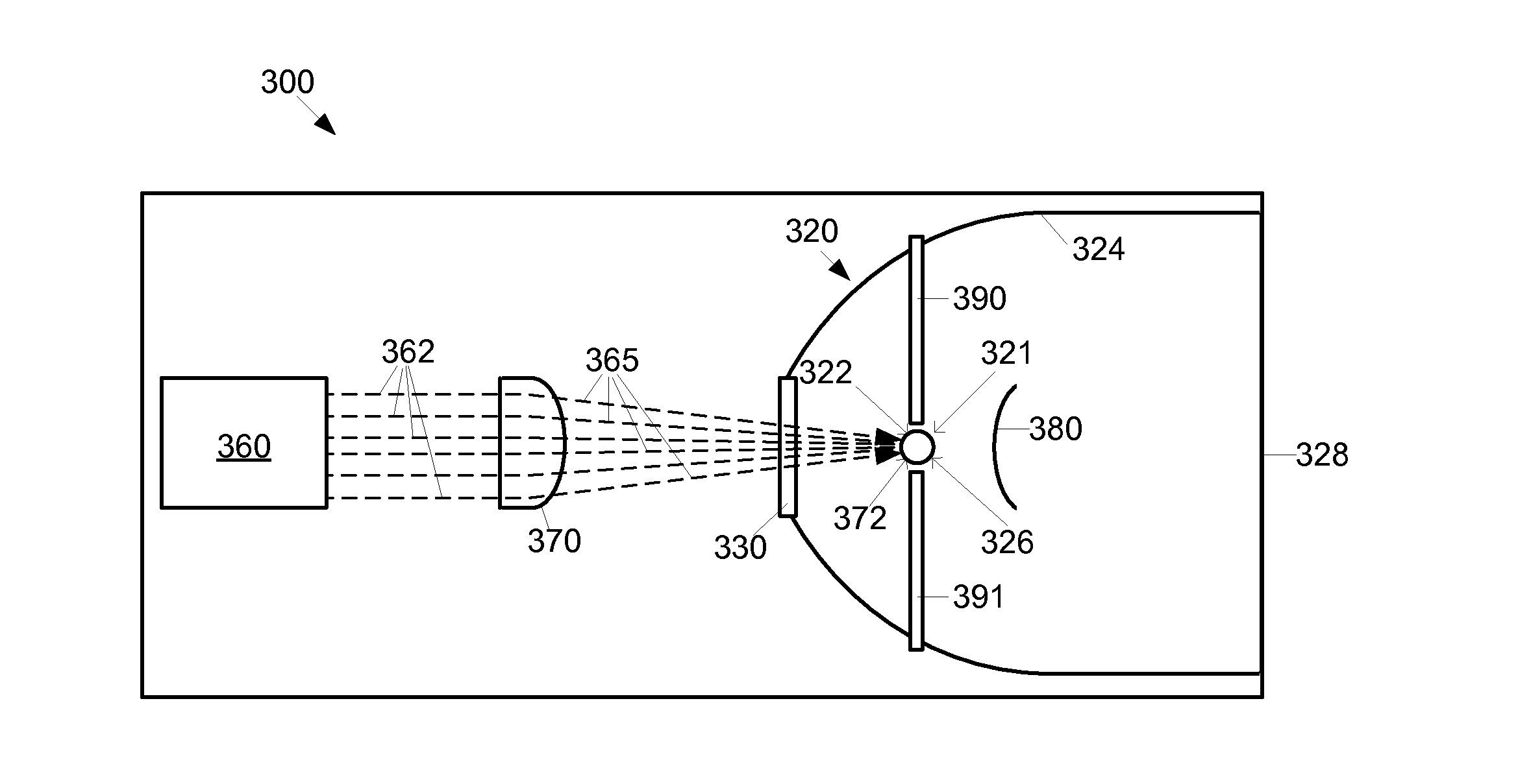
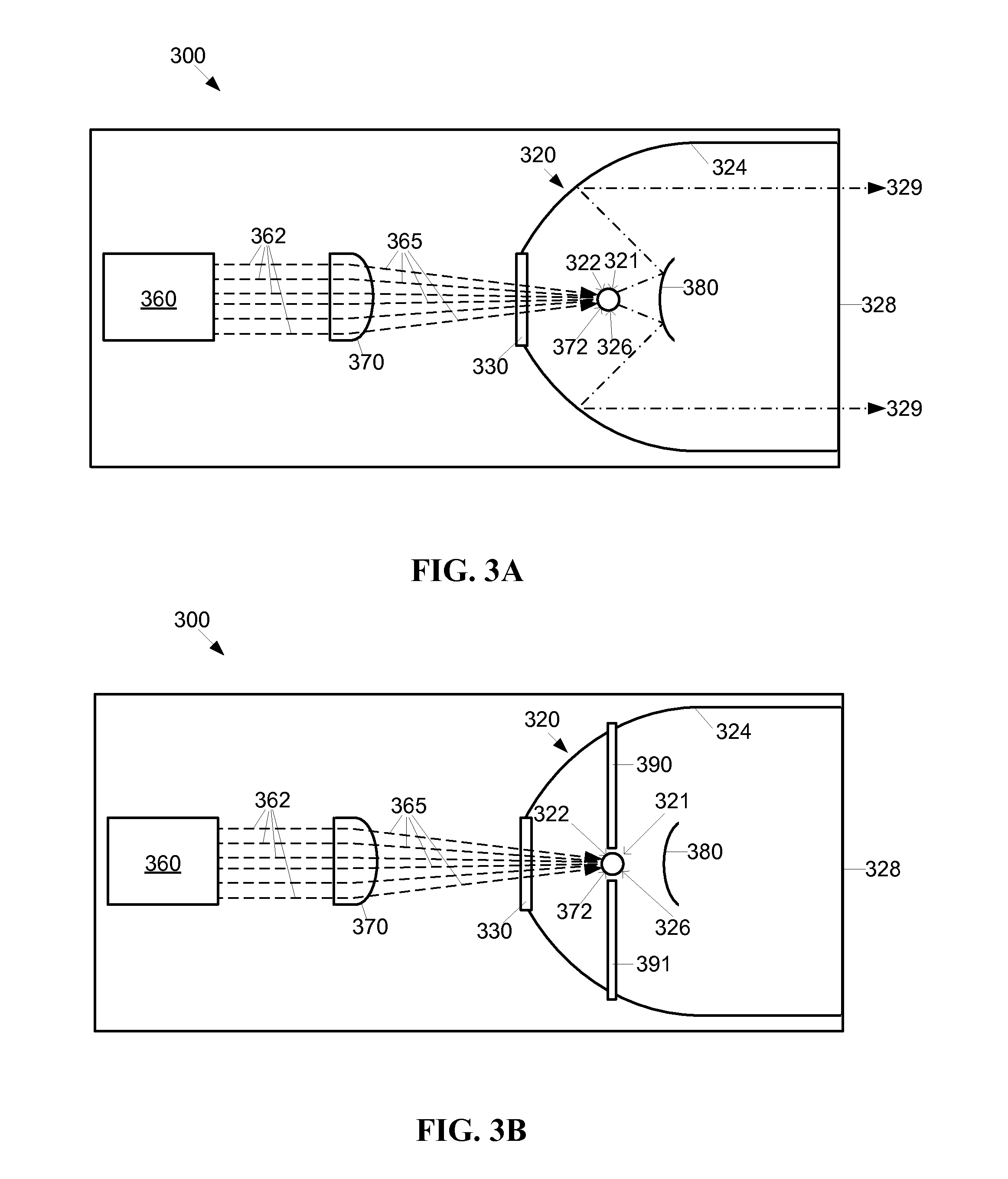
The present invention provides a laser driven sealed beam lamp, which is a high intensity illumination device. The device has a sealed chamber with an ingress window, plasma sustaining region, plasma ignition region, and a high intensity light egress window. The chamber has an interior surface that reflects high intensity light from the plasma sustaining region to the egress window. The laser beam from the laser light source directly enters the chamber through the lens and ingress window. The technical effect of this invention is a sealed beam lamp that emits high intensity light through a direct path of the laser beam, resulting in improved efficiency and overall performance.

Problems solved by technology

The anode and / or cathode may wear and emit particles.
Such particles can impair the operation of the lamp, and cause degradation of the anode and / or cathode.
Unfortunately, the curved lamp surface distorts the beam of the laser.
A distortion of the beam results in a focal area that is not crisply defined.
While this distortion may be partially corrected by inserting optics between the laser and the curved surface of the lamp, such optics increase cost and complexity of the lamp, and still do not result in a precisely focused beam.

Method used


Image

  • Laser Driven Sealed Beam Lamp
  • Laser Driven Sealed Beam Lamp
  • Laser Driven Sealed Beam Lamp

Examples


first embodiment

[0044]The high intensity egress light 329 output by the lamp 300 is emitted by a plasma formed of the ignited and energized ionizable medium within the chamber 320. The ionizable medium is ignited within the chamber 320 by one of several means, as described further below, at a plasma ignition region 321 within the chamber 320. For example, the plasma ignition region 321 may be located between a pair of ignition electrodes (not shown) within the chamber 320. The plasma is continuously generated and sustained at a plasma generating and / or sustaining region 326 within the chamber 320 by energy provided by ingress laser light 365 produced by a laser light source 360 located within the lamp300 and external to the chamber 320. In the first embodiment, the plasma sustaining region 326 and the plasma ignition region 321 are co-located with a focal point 322 of the interior surface 324 at a fixed location. In alternative embodiments the laser light source 360 may be external to the lamp 300....

second embodiment

[0058]FIGS. 4C and 4D show implementations of the second embodiment incorporating an optional reflector 380. The reflector 380 may be relocated between an ignition position, shown in FIG. 4C and a sustaining position, shown in FIG. 4D. The reflector 380 may be located in an ignition position out of the way of the path of the focused ingress laser light 365 from the ingress window 330 to the plasma ignition region 421. For example, the reflector 380 may be pivoted or retracted (translated) from the sustaining position shown in FIG. 4D, to the ignition position closer to the wall of the chamber interior surface 324, as shown in FIG. 4C.

[0059]Alternatively, the reflector 380 may remain stationary in the sustaining position as lens focal region 372 is adjusted. In such an embodiment, the location of the ignition electrodes 490, 491 may be closer to the proximal end of the chamber 320 than the distal end of the chamber 320.

[0060]FIGS. 4E and 4F show a variation of the second embodiment w...

third embodiment

[0064]The ingress lens 570 is disposed in the path between the laser light source 560 and an ingress lens focal region 572 within the chamber 520. For example, the ingress lens 570 may be configured to direct collimated laser light 532 emitted by the laser light source 560 to the ingress lens focal region 572. In the third embodiment, the ingress lens focal region 572 is co-located with the plasma sustaining region 326, the plasma ignition region 321, and the focal point 322 of the interior surface 524. The interior surface and / or the exterior surface of the ingress lens 530 may be treated to reflect the high intensity light generated by the plasma, while simultaneously permitting passage of the laser light 565 into the chamber 520.

[0065]The lamp 500 may include internal features such as a reflector 380 and high intensity egress light paths 329 as described above regarding the first embodiment. The path of the laser light 532, 565 from the laser light source 360 through the ingress ...


PUM


Abstract

A method and apparatus for a sealed high intensity illumination device are disclosed. The device is configured to receive a laser beam from a laser light source. The device has a sealed chamber configured to contain an ionizable medium. The chamber has a substantially flat ingress window disposed within a wall of the integral reflective chamber interior surface configured to admit the laser beam into the chamber, a plasma sustaining region, a plasma ignition region, and a high intensity light egress window configured to emit high intensity light from the chamber. The chamber has an integral reflective chamber interior surface configured to reflect high intensity light from the plasma sustaining region to the egress window. There is a direct path of the laser beam from the laser light source through the lens and ingress window to the lens focal region.

Description

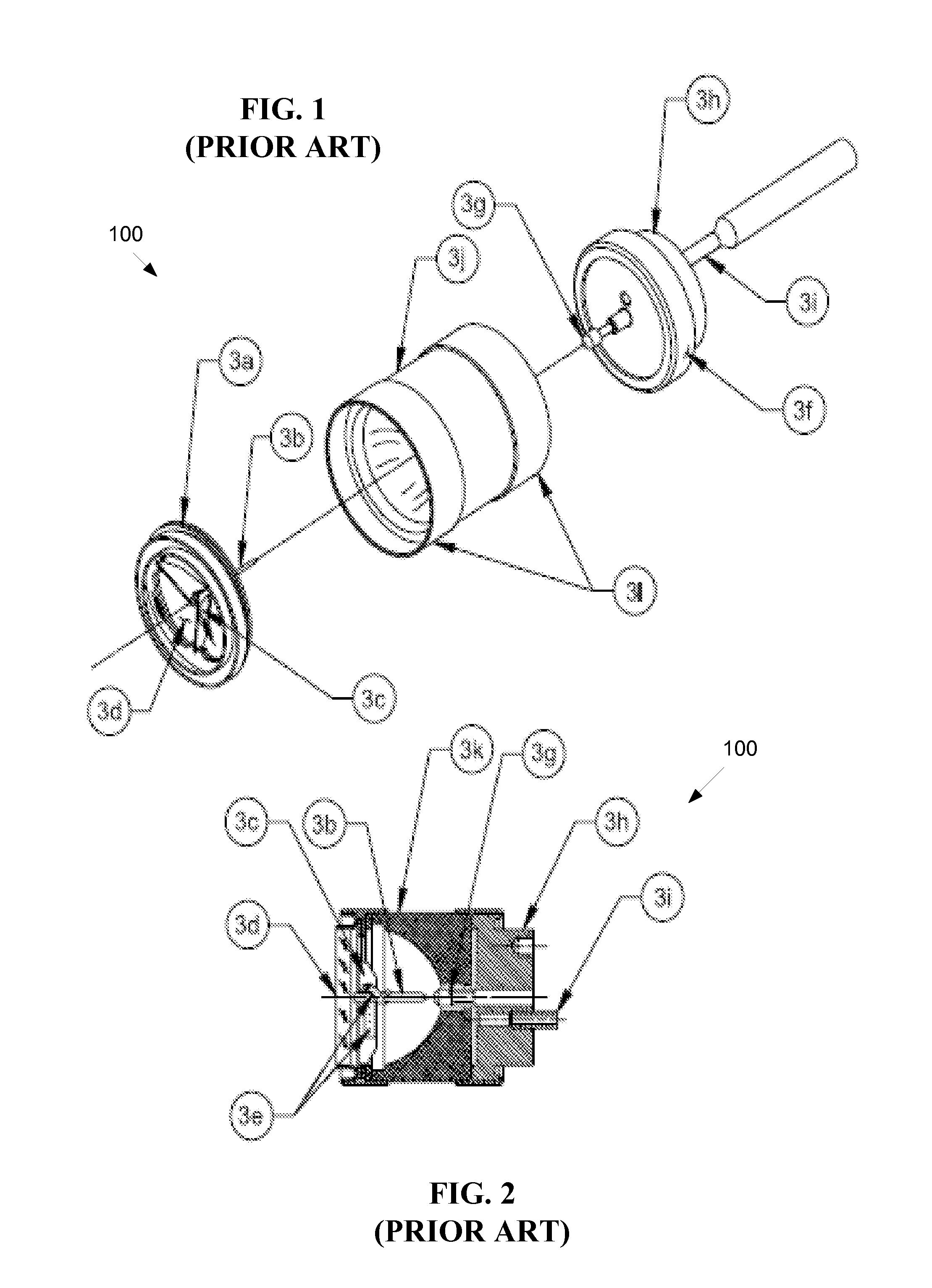
CROSS-REFERENCE TO RELATED APPLICATIONS[0001]This application claims the benefit of U.S. Provisional Patent Application Ser. No. 61 / 993,735, filed May 15, 2014, entitled “Laser Driven Sealed Beam Xenon Lamp” which is incorporated by reference herein in its entirety.FIELD OF THE INVENTION[0002]The present invention relates to illumination devices, and more particularly, is related to high-intensity arc lamps.BACKGROUND OF THE INVENTION[0003]High intensity arc lamps are devices that emit a high intensity beam. The lamps generally include a gas containing chamber, for example, a glass bulb, with an anode and cathode that are used to excite the gas (ionizable medium) within the chamber. An electrical discharge is generated between the anode and cathode to provide power to the excited (e.g. ionized) gas to sustain the light emitted by the ionized gas during operation of the light source.[0004]FIG. 1 shows a pictorial view and a cross section of a low-wattage parabolic prior art Xenon lam...

Claims


Application Information

Patent Timeline
Patent Type & Authority Applications(United States)
IPC IPC(8): H01J61/02H01J61/30H01J61/16
CPCH01J61/025H01J61/30H01J61/16H01J61/24H01J61/33H01J61/35H01J61/54H01J65/04H01J61/361H01J61/26H01J61/547H05G2/008
Inventor BLONDIA, RUDI
Owner EXCELITAS TECH
Learn More