Motor of a Ceiling Fan

a ceiling fan and motor technology, applied in the direction of machines/engines, bearing unit rigid supports, liquid fuel engines, etc., can solve the problems of increasing assembly difficulty, time-consuming, complex process for manufacturing the motor, etc., and achieve the effect of simplifying the assembly steps

Active Publication Date: 2015-11-19
SUNONWEALTH ELECTRIC MACHINE IND
View PDF12 Cites 35 Cited by
  • Summary
  • Abstract
  • Description
  • Claims
  • Application Information

AI Technical Summary

Benefits of technology

[0008]What is needed is a motor of a ceiling fan, which needs not to connect t

Problems solved by technology

Therefore, the process for manufacturing the motor 9 is thus complicated and time consumptive.
Besides, the awkwardly big-sized motor 9 also increases the difficulty in assembly and thus raises the manufacture cost.
This vibration may therefore largel

Method used


Image

  • Motor of a Ceiling Fan
  • Motor of a Ceiling Fan
  • Motor of a Ceiling Fan

Examples


first embodiment

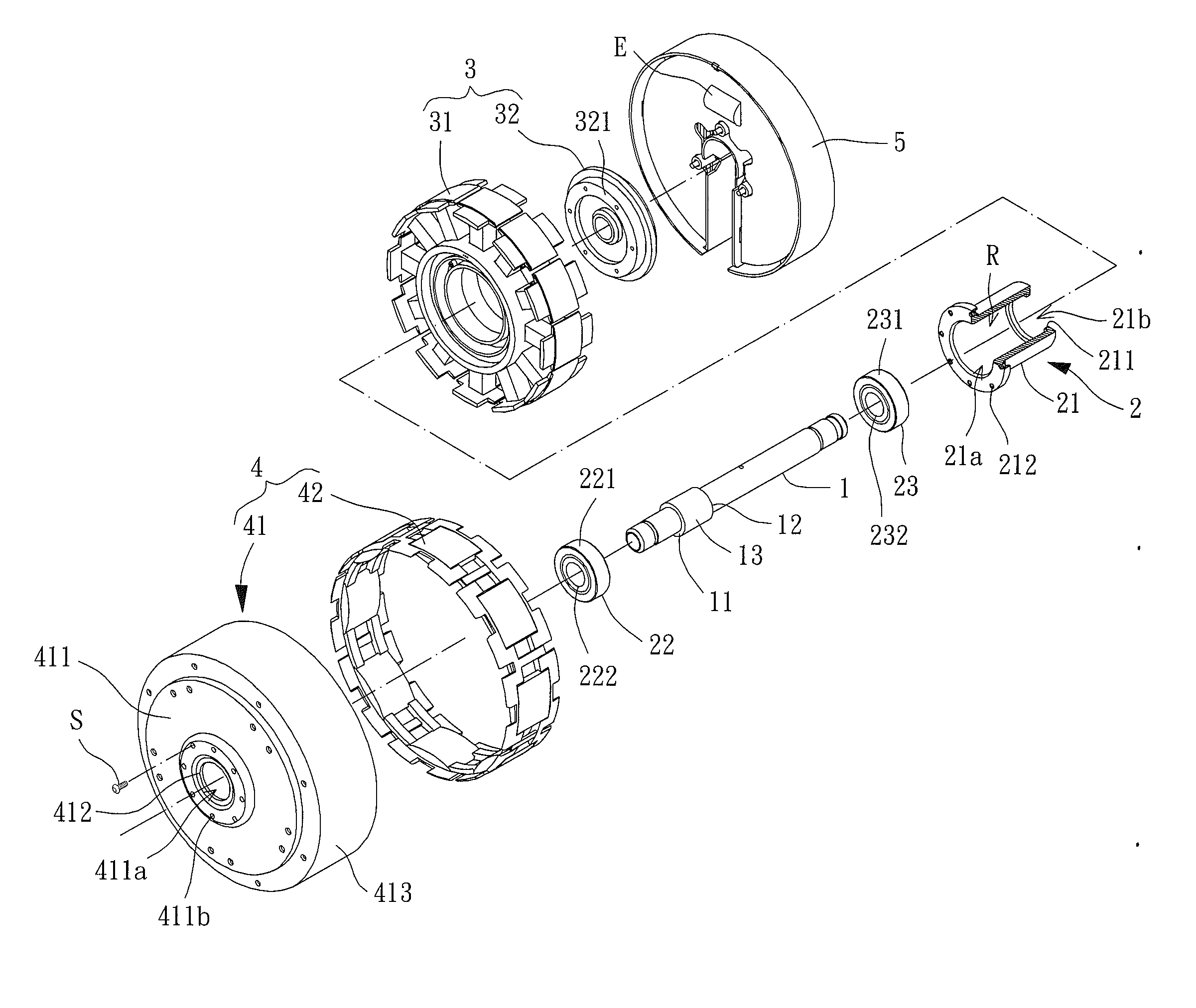
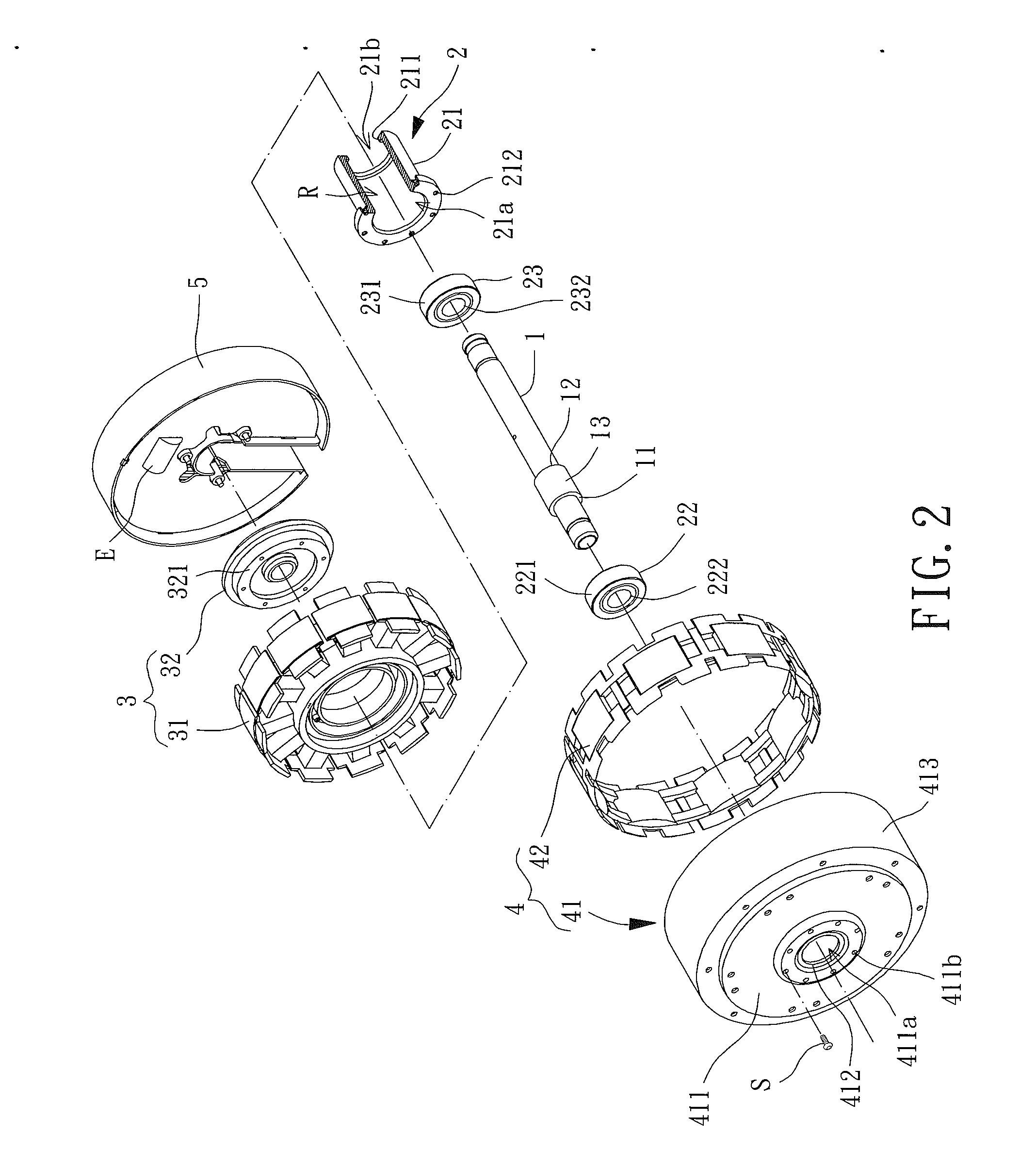
[0025]The motor of the first embodiment further includes a stator 3 and a rotor 4. The stator 3 has a core 31 directly or indirectly coupling with the shaft 1. The rotor 4 has a housing 41 connecting with the bearing sleeve 21. The housing 41 may be adapted to couple with blades of the ceiling fan.

[0026]The housing 41 has a base 411 and a connecting portion 412, with the first shoulder surface 11 facing the base 411 and located between the base 411 and the second shoulder surface 12. In other words, since the first and second shoulder surfaces 11, 12 face the first and second openings 21a, 21b respectively, the first shoulder surface 11, first opening 21a and first bearing 22 are close to the base 411, and the second shoulder surface 12, second opening 21b and second bearing 23 are away from the base 411. The center of the base 411 has a through hole 411a aligning with the first and second openings 21a, 21b in the axial direction of the shaft 1, so that the shaft 1 can penetrate the...

second embodiment

[0039]With the above illustrated structures, when an assembly process for combining the bearing assembly 2 and the shaft 1 of the disclosed motor is performed, the shaft 1 is extended through the first and second bearings 22, 23 by two ends respectively and thus abuts against the inner rings 222, 232 by the first and second shoulder surfaces 11, 12. The bearing sleeve 21 is then coupled to the outer rings 221, 231, with the annular flange 211 abutting against the outer ring 221 of the first bearing 22. Finally, the housing 41 couples with the bearing sleeve 21 and thus the connecting portion 412 abuts against the outer ring 231 of the second bearing 23. Therefore, with the first shoulder surface 11 and the annular flange 211 axially clamping the first bearing 22, and with the second shoulder surface 12 and the connecting portion 412 axially clamping the second bearing 23, the first and second bearings 22, 23 can be firmly positioned in the motor. Accordingly, the inner rings 222, 23...


PUM


Abstract

A motor of a ceiling fan includes: a shaft having two shoulder surfaces facing in opposite axial directions of the shaft, with the shaft coupling with a stator; a bearing sleeve receiving two bearings for supporting the shaft, with an annular flange formed at an end of the bearing sleeve, wherein the annular flange and one of the shoulder surfaces of the shaft clamp and position one of the bearings; and a rotor having a housing coupling with the bearing sleeve, with the housing having a connecting portion, wherein the connecting portion and the other one of the shoulder surfaces of the shaft clamp and position the other one of the bearings.

Description

BACKGROUND OF THE INVENTION[0001]1. Field of the Invention[0002]The present invention generally relates to a motor of a ceiling fan and, more particularly, to a motor able to receive a plurality of bearings by one bearing sleeve.[0003]2. Description of the Related Art[0004]Referring to FIG. 1, a conventional motor of a ceiling fan with a reference number of “9,” an U.S. Pat. No. 7,615,898, and entitled as “INTEGRATED STATOR AND ROTOR FOR A DC BRUSHLESS CEILING FAN MOTOR” is shown, which includes a stator 91 and a rotor 92. The stator 91 has a core 911, a plurality of coils 912 winds on the core 911, and a shaft 913 passing through the core 911. The rotor 92 has an upper shield 921, a lower shield 922 and a waist ring 923 sandwiched by the upper and lower shields 921, 922. Each of the upper and lower shields 921, 922 combines with a bearing 924 for the shaft 913 to couple with, and the stator 91 is received in a room defined by the upper shield 921, lower shield 922 and waist ring 92...

Claims


Application Information

Patent Timeline
IPC IPC(8): H02K5/16H02K7/00H02K5/04F16C35/063H02K5/24
CPCH02K5/165F16C35/063H02K7/003H02K5/04H02K5/24F04D25/062F04D25/088H02K5/1737F16C35/06F16C19/54F16C2380/26F04D29/646H02K5/173
Inventor YIN, TSO-KUOSHAN, DUO-NIANCHIOU, BO-WEILU, YU-YUAN
Owner SUNONWEALTH ELECTRIC MACHINE IND
Why Eureka
Try Eureka