
Dynamic Configured Video Camera

a video camera and dynamic configuration technology, applied in the field of cameras, can solve the problems of small correction matrix, small computing capacity, and restricted image processing possibilities, and achieve the effect of reducing the overall calculation work

Active Publication Date: 2015-11-19
MOBOTIX
View PDF6 Cites 7 Cited by
  • Summary
  • Abstract
  • Description
  • Claims
  • Application Information

AI Technical Summary

Benefits of technology

The patent proposes a method for reconfiguring a logic cell arrangement used for camera data preparation without interring video data preparation and reproduction. The dynamic reconfiguration allows for monitoring video data streams for security purposes without causing adverse effects. The method allows for quick and efficient correction matrix calculations, with changes to PTZ parameters being made in real-time, and the overall image data can be quickly adapted to changes in camera configuration. The technical effect of the invention is to provide a flexible and efficient method for processing camera data, particularly in the case of PTZ-capable cameras.

Problems solved by technology

It is obvious that very small correction matrices require very little computing.
If only a 2×2 matrix is used for the correction, only four parameters per output pixel must be determined for calculating the configuration data, but the image processing possibilities are typically restricted.

Method used


Image

  • Dynamic Configured Video Camera
  • Dynamic Configured Video Camera
  • Dynamic Configured Video Camera

Examples


Embodiment Construction

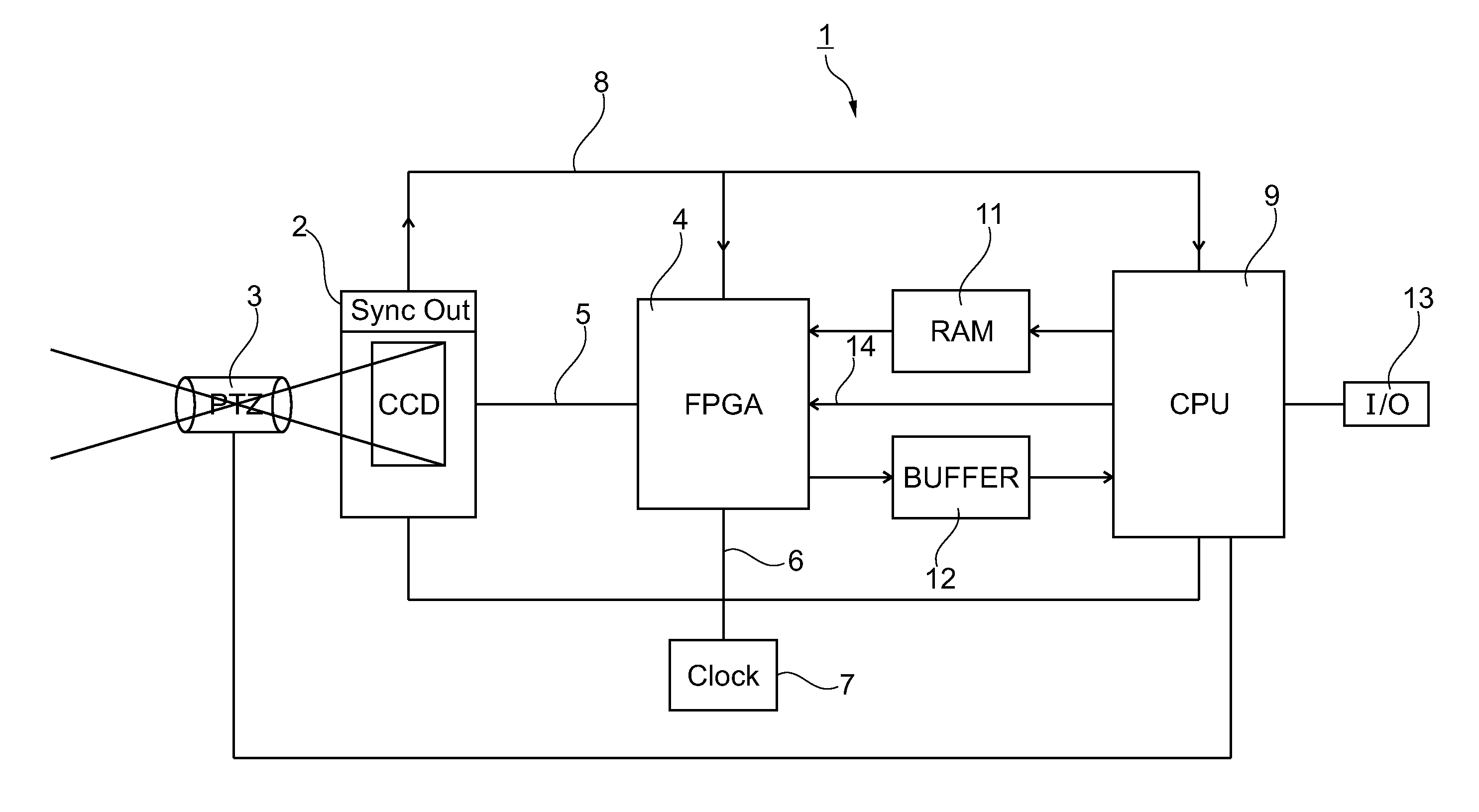
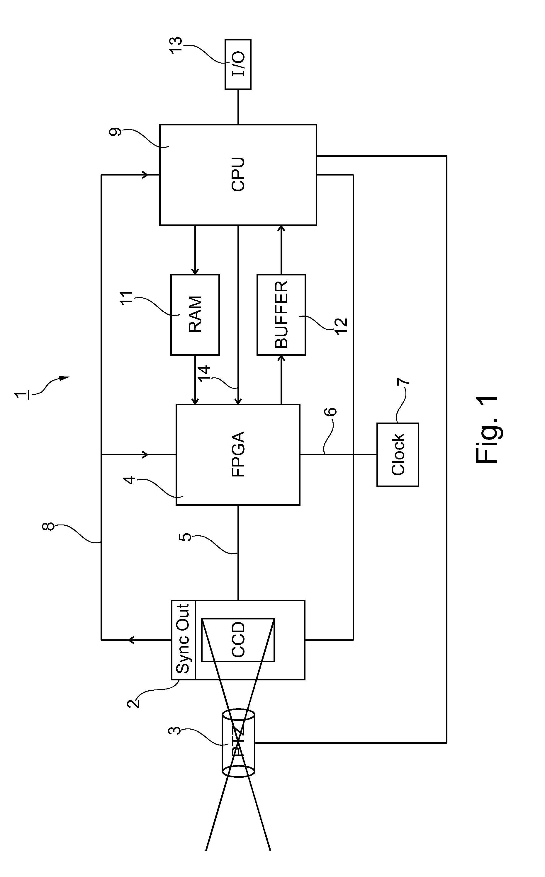
[0044]According to FIG. 1, a video camera arrangement, which is generally referred to as 1, comprises an image sensor 2 which detects environmental images by means of a zoom-capable lens 3 and can be panned and tilted therewith so that a PTZ-capable image recording is guaranteed. The video camera arrangement 1 further comprises an FPGA 4 as reconfigurable logic cell arrangement, wherein, if applicable, the FPGA 4 receives from the image sensor 2 conditioned video raw data via a line 5, receives clock signals from a clock source 7 via a clock line 6, receives video sync signals, namely in the embodiment—here line synchronization signals—and full image synchronization signals via a line 8 from the image sensor 2 which, in the embodiment of FIG. 1, also sends synchronization signals to a CPU 9 which in turn receives signals from the clock generator 7 via the line 6, stores configuration data for the FPGA 4, as will be described below, in a random access memory (RAM) 11 and receives pro...


PUM


Abstract

A method for providing video data streams is disclosed. In an embodiment the method includes generating video image data by a digitally adjustable video camera arrangement and preparing the video image data by a reconfigurable logic cell arrangement, wherein during camera operation, settings of the video camera arrangement are changed, adapted reconfiguration data for the reconfigurable logic cell arrangement are calculated in view of the amended settings and provided to the logic cell arrangement, and wherein the logic cell arrangement is configured with the reconfiguration data at runtime.

Description

[0001]This patent application claims the priority of German patent application 10 2014 208 771.6, filed May 9, 2014, and is incorporated herein by reference in its entirety.TECHNICAL FIELD[0002]The present application relates to cameras and in particular to video cameras.BACKGROUND[0003]Video cameras, in particular video cameras which are used for monitoring purposes, should provide a large volume of image data with the power consumption being as low as possible. However, the data processing tasks are significant. They include, i.e., the preparation of the raw data from an image sensor, for example, the generation of a color image on the basis of the color image recorded by using a Bayer filter, denoising, the performance of gamma corrections, the compression of individual images, e.g., by means of JPEG algorithms, the M×PEG method and the like, the compression of image data video streams in view of image parts that are not of interest, image parts with at the most marginal changes ...

Claims


Application Information

Patent Timeline
Patent Type & Authority Applications(United States)
IPC IPC(8): H04N5/232
CPCH04N5/23209H04N5/23225H04N5/06H04N5/2628H04N23/617H04N23/62H04N23/698H04N23/69H04N23/663
Inventor HINKEL, RALF
Owner MOBOTIX
Learn More