
Joining process for neutron absorbing materials

a technology of neutron absorbing materials and joining processes, which is applied in nuclear engineering, manufacturing tools, cooking vessels, etc., can solve the problems of reducing the overall neutron capture capability of the fuel basket, preventing designers from fully exploiting their potential, and reducing the thermal conductivity of the fuel bask

Inactive Publication Date: 2015-11-26
HOLTEC INT
View PDF5 Cites 7 Cited by
  • Summary
  • Abstract
  • Description
  • Claims
  • Application Information

AI Technical Summary

Benefits of technology

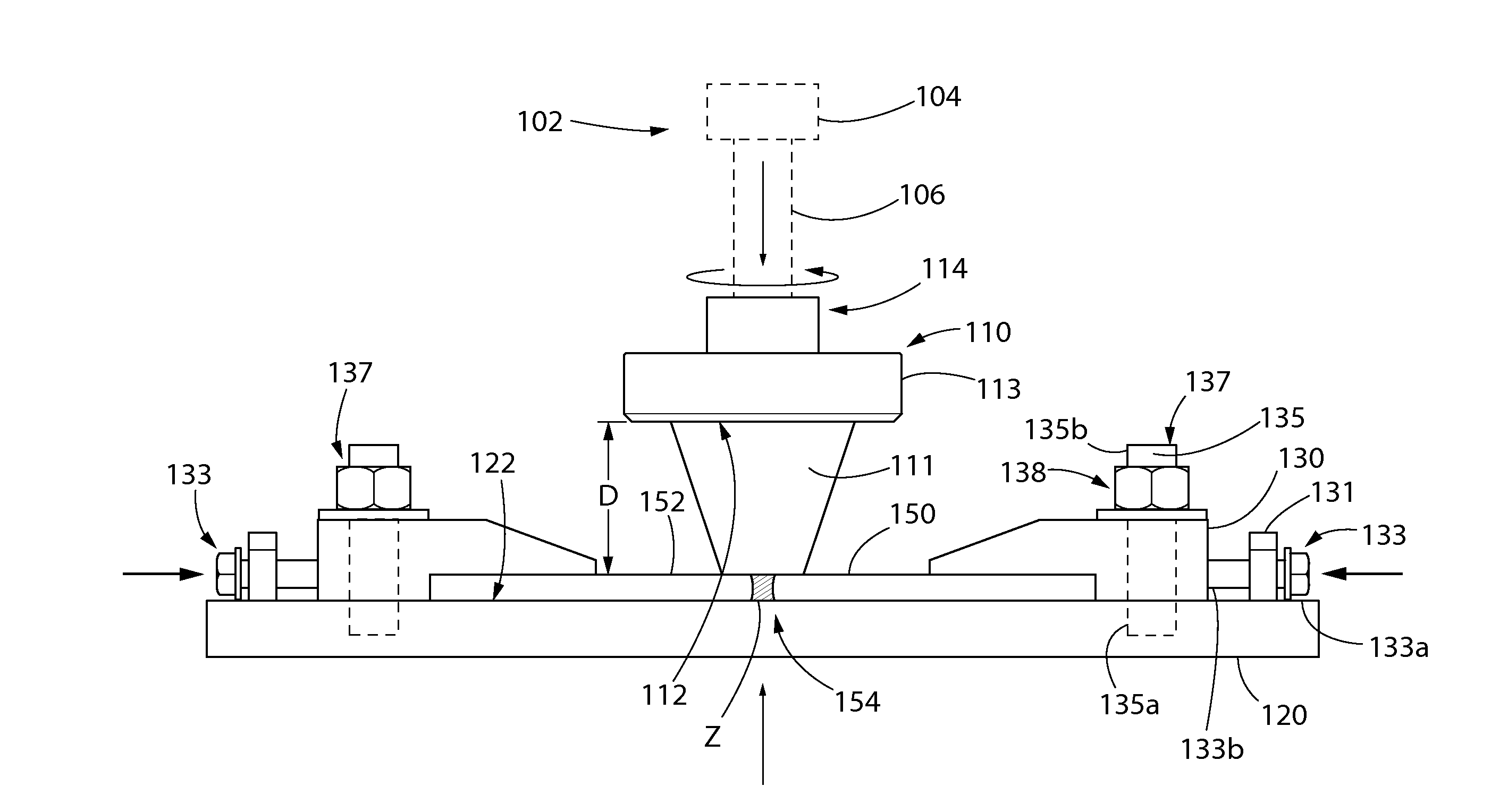
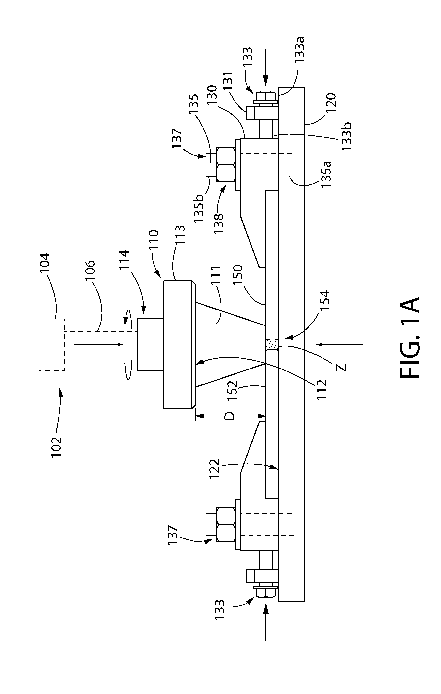
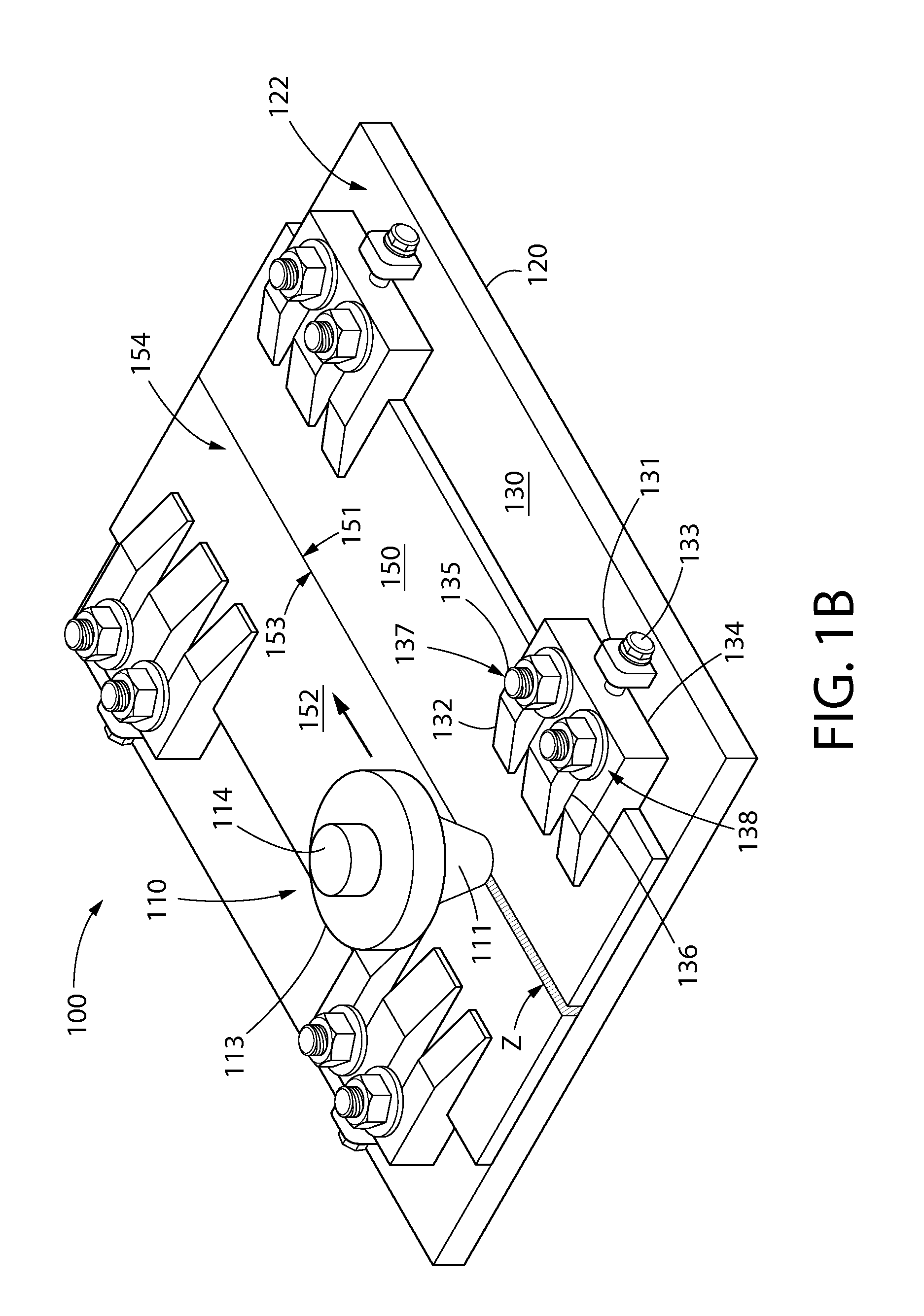
The present invention provides a process and apparatus for joining Metal Matrix Composite (MMC) material to itself or other materials, such as aluminum, without the need for pre-placed filler material. This is achieved by using a specially designed tool that applies pressure while simultaneously melting and stirring the MMC material in the plastic state. The joining process produces weld joints that are strong and ductile, with similar strength to the MMC base materials. The technical effect of this invention is the ability to join MMC material to other non-boron containing materials, such as aluminum, to create a uniform cross-section of composite material.

Problems solved by technology

The MMCs, however, suffer from a serious limitation—lack of weldability—which has prevented designers from fully exploiting their potential in designing compact nuclear fuel storage devices.
This is an unsatisfactory aspect of the state of the art for several reasons, including: (1) the thermal conductivity of the fuel basket is reduced by the presence of stainless steel; and (2) stainless steel occupies valuable cross section space where the boron bearing MMC would be, thus reducing the overall neutron capture capability of the fuel basket.
Unfortunately, tests show that welding by classical MIG or TIG processes fails to produce a high quality joint, which is attributed to the boron carbide particles situated on the grain boundaries in the MMC plates.

Method used


Image

  • Joining process for neutron absorbing materials
  • Joining process for neutron absorbing materials
  • Joining process for neutron absorbing materials

Examples


Embodiment Construction

[0024]The features and benefits of the invention are illustrated and described herein by reference to exemplary embodiments. This description of exemplary embodiments is intended to be read in connection with the accompanying drawings, which are to be considered part of the entire written description. Accordingly, the disclosure expressly should not be limited to such exemplary embodiments illustrating some possible non-limiting combination of features that may exist alone or in other combinations of features.

[0025]In the description of embodiments disclosed herein, any reference to direction or orientation is merely intended for convenience of description and is not intended in any way to limit the scope of the present invention. Relative terms such as “lower,”“upper,”“horizontal,”“vertical,”, “above,”“below,”“up,”“down,”“top” and “bottom” as well as derivative thereof g “downwardly,”“upwardly,” etc.) should be construed to refer to the orientation as then described or as shown in ...


PUM

PropertyMeasurementUnit
Temperatureaaaaaaaaaa
Fractionaaaaaaaaaa
Angleaaaaaaaaaa

Abstract

A method and associated system for joining workpieces formed of neutron absorbing materials. The method includes positioning first and second workpieces together to form a joint, heating the first and second workpieces at the joint to a plastic condition, intermingling plastic material from the first and second workpieces together at the joint, and cooling the intermingled plastic material to a solid state forming a welded fusion zone comprised of material from the first and second metal matrix composite workpieces. The workpiece material at the joint is not melted by the heating. The heating may be perforated by frictionally heating the materials with a rotary tool, in one non-limiting embodiment, the neutron absorbing workpieces may be formed of metal matrix composites comprising aluminum or aluminum alloy and boron carbide.

Description

CROSS-REFERENCE TO RELATED APPLICATIONS[0001]The present application claims the benefit of U.S. Provisional Patent Application Ser. No. US 61 / 746,294 filed Dec. 27, 2012, which is incorporated herein by reference in its entirety.FIELD OF THE INVENTION[0002]The present invention relates to material joining processes, and more particularly to a welding process suitable for joining materials usable in the nuclear power generation industry having neutron absorbing properties.BACKGROUND OF THE INVENTION[0003]Metal matrix composites (MMCs) made with aluminum or aluminum alloy powder mixed with embedded particles of boron carbide have become quite popular neutron absorber materials in the nuclear power industry because of their essentially porosity-free body and their ability to hold a large percentage of boron carbide (a neutron poison). For example, Metamic disclosed in U.S. Pat. No. 6,042,779, incorporated herein by reference in its entirety, is routinely manufactured with boron carbide...

Claims


Application Information

Patent Timeline
IPC IPC(8): B23K20/12B23K20/233
CPCB23K20/2333B23K20/122B23K20/129G21F5/012
Inventor SINGH, KRISHNA P.MECKLEY, JOSEPH ALBERTZSIDAI, LASZLO
Owner HOLTEC INT
Learn More