Work machine

Active Publication Date: 2015-11-26
MAKINO MILLING MASCH CO LTD
View PDF5 Cites 0 Cited by
  • Summary
  • Abstract
  • Description
  • Claims
  • Application Information

AI Technical Summary

Benefits of technology

[0013]According to the invention, the arrangement of the feed screw of the vertically driving means disposed over the supporting means for supporting the bed on the floor, and the feed motor connected to the lower end of the feed screw allows the supporting means to receive directly the downward force acting on the bearing element of the feed screw and the motor bracket. Accordingly, the rigidity of the machine tool is increased. If the feed screw and the supporting means are apart from each other, a highly rigid and heavy bed is

Problems solved by technology

As a result, the stability of the machine tool is degraded and the over-al

Method used


Image

  • Work machine
  • Work machine
  • Work machine

Examples


Example

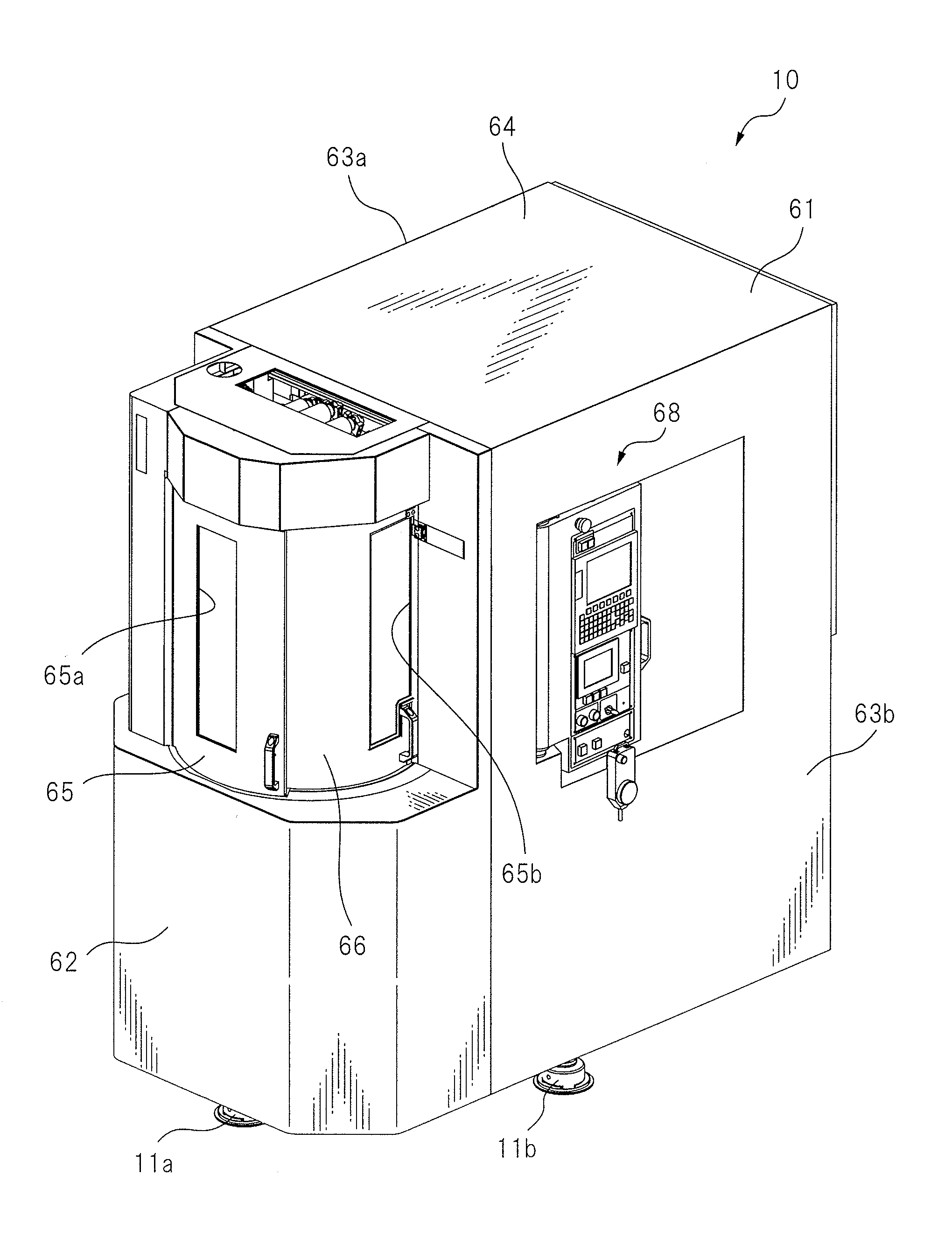
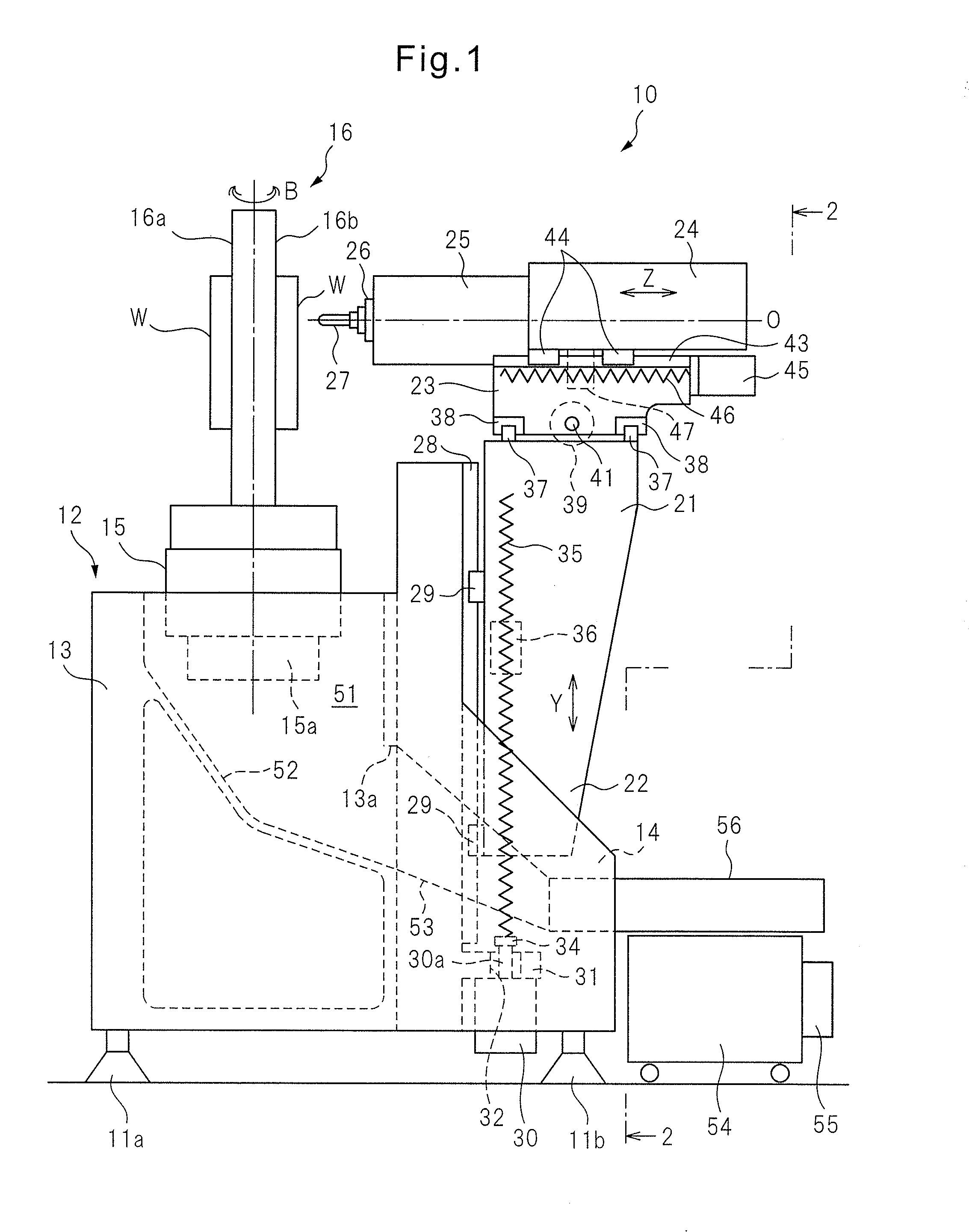
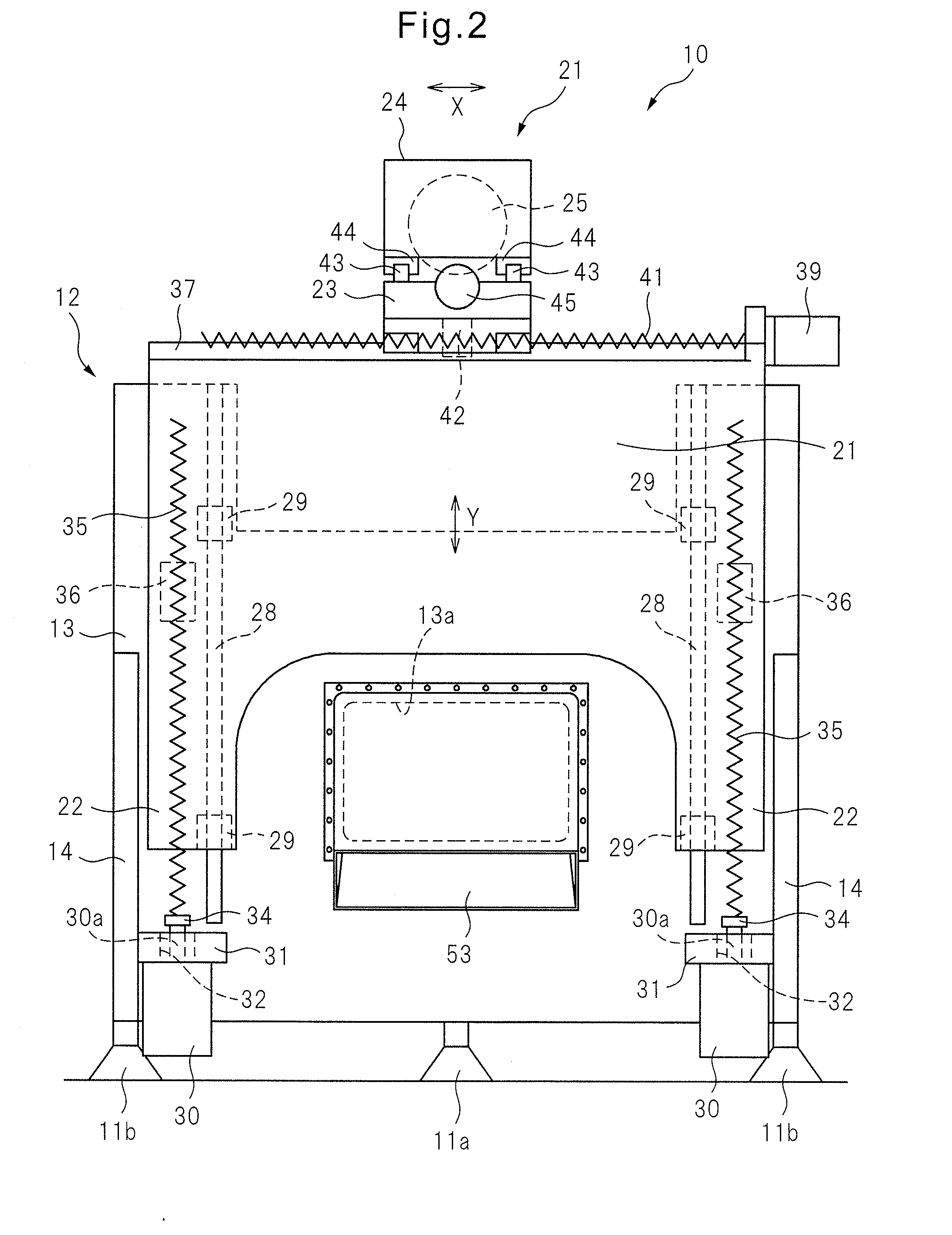
[0017]With reference to the drawings, an embodiment of the invention will be described below. FIG. 1 is a side view schematically showing the structure of a machine tool according to an embodiment of the invention. FIG. 2 is a rear view of the machine tool viewing in the direction of arrows 2-2 in FIG. 1. FIG. 3 is a perspective view schematically showing the exterior of the machine tool with a splashguard. In this specification, a front side of the machine tool is defined by the direction of the tip of a tool attached to the end of a spindle as described below.

[0018]In this embodiment, as an example, a machine tool 10 may be a four-axis horizontal machining center having liner feed axes extending in three orthogonal X-, Y- and Z-axes directions and a B-axis providing a rotary feed axis. The left-right direction (perpendicular to the plane of FIG. 1) of the machine tool 10 is defined as the X-axis, the vertical direction is defined as the Y-axis, and the front-rear direction (the le...


PUM


Abstract

A work machine includes: a bed having a table positioned on the upper surface thereof; sidewalls positioned to the left and right of the bed and projecting to the rear of the rear surface of the bed; support members for each supporting the bed in relation to a floor surface by using two points on the sidewalls to the left and right of the bed, and using at least one other point; a vertically moving body for moving along a pair of left and right vertical guides positioned in the vertical direction down to the vicinity of the floor surface on the rear surface of the bed; and a vertical drive means for moving the vertically moving body as one of the abovementioned relative movements, and having a pair of left and right feed screws positioned in parallel with the vertical guides.

Description

CROSS REFERENCE TO RELATED APPLICATIONS[0001]This application is a U.S. National Phase patent application of PCT / JP2012 / 066180, filed on Jun. 25, 2012, which is hereby incorporated by reference in the present disclosure in its entirety.FIELD OF THE INVENTION[0002]The invention relates to a machine tool for processing a workpiece by moving a tool attached to a spindle and the workpiece attached to a table relative to each other.BACKGROUND OF THE INVENTION[0003]Generally, in machine tools, there are various types of configuration for moving a spindle and a tale in X-, Y- and Z-axes. Depending on the configuration, X-, Y- and Z-axes moving bodies, X-, Y- and Z-axes guides, X-, Y- and Z-axes feeding drives and a chip remover are appropriately arranged.[0004]In a machine tool of Patent Document 1, the respective moving bodies movable in X-, Y- and Z-axes directions are disposed on a rear face of a base. A feeding mechanism for vertically moving a body along guide rails is disposed over t...

Claims


Application Information

Patent Timeline
IPC IPC(8): B23Q5/40B23Q1/44B23Q1/01
CPCB23Q5/40B23Q1/44B23Q1/015B23Q1/626B23Q1/017B23Q11/0053B23Q11/0067Y02P70/10Y10T409/30392
Inventor SUZUKI, TOSHIHIROMAYUMI, KAZUYAKOBAYASHI, SATOSHI
Owner MAKINO MILLING MASCH CO LTD
Why Eureka
Try Eureka