Unmanned aerial vehicle and fuselage thereof and method for manufacturing the fuselage

a technology for unmanned aerial vehicles and fuselages, applied in the field of aircraft, can solve the problems of increasing affecting preventing reasonable use of space in the housing, etc., and achieves the effects of facilitating maintenance and replacement of components, reducing the weight and improving the flying performance of unmanned aerial vehicles

Active Publication Date: 2015-11-26
SHENZHEN AEE TECH
View PDF4 Cites 84 Cited by
  • Summary
  • Abstract
  • Description
  • Claims
  • Application Information

AI Technical Summary

Benefits of technology

[0006]The main purpose of the invention is to provide a fuselage of an unmanned aerial vehicle to reduce a weight of the unmanned aerial vehicle as a whole and thus to improve the flying performance of the unmanned aerial vehicle and to facilitate the maintenance and replacement of a component of the unmanned aerial vehicle.

Problems solved by technology

However, the unmanned aerial vehicle has following drawbacks: the housing generally includes a front housing and a rear housing which are secured together by a large number of screws, which greatly increases the weight of the unmanned aerial vehicle and affects the flying performance of the unmanned aerial vehicle;
moreover, it is inconvenient to assemble and disassemble the housings, making the maintenance and replacement of the component inside the housing troublesome; in addition, signal shielding between two modules inside the housing is weak and interference is generally produced between the modules, which affects the quality of the signal transmission of each module and may even affects the flying safety of the unmanned aerial vehicle; furthermore, the arrangement of the modules inside the housing is unreasonable, preventing the space of the housing from being utilized reasonably.

Method used


Image

  • Unmanned aerial vehicle and fuselage thereof and method for manufacturing the fuselage
  • Unmanned aerial vehicle and fuselage thereof and method for manufacturing the fuselage
  • Unmanned aerial vehicle and fuselage thereof and method for manufacturing the fuselage

Examples


Embodiment Construction

[0038]It should be understood that the embodiments described herein are only used to explain the present disclosure rather than to limit the present disclosure.

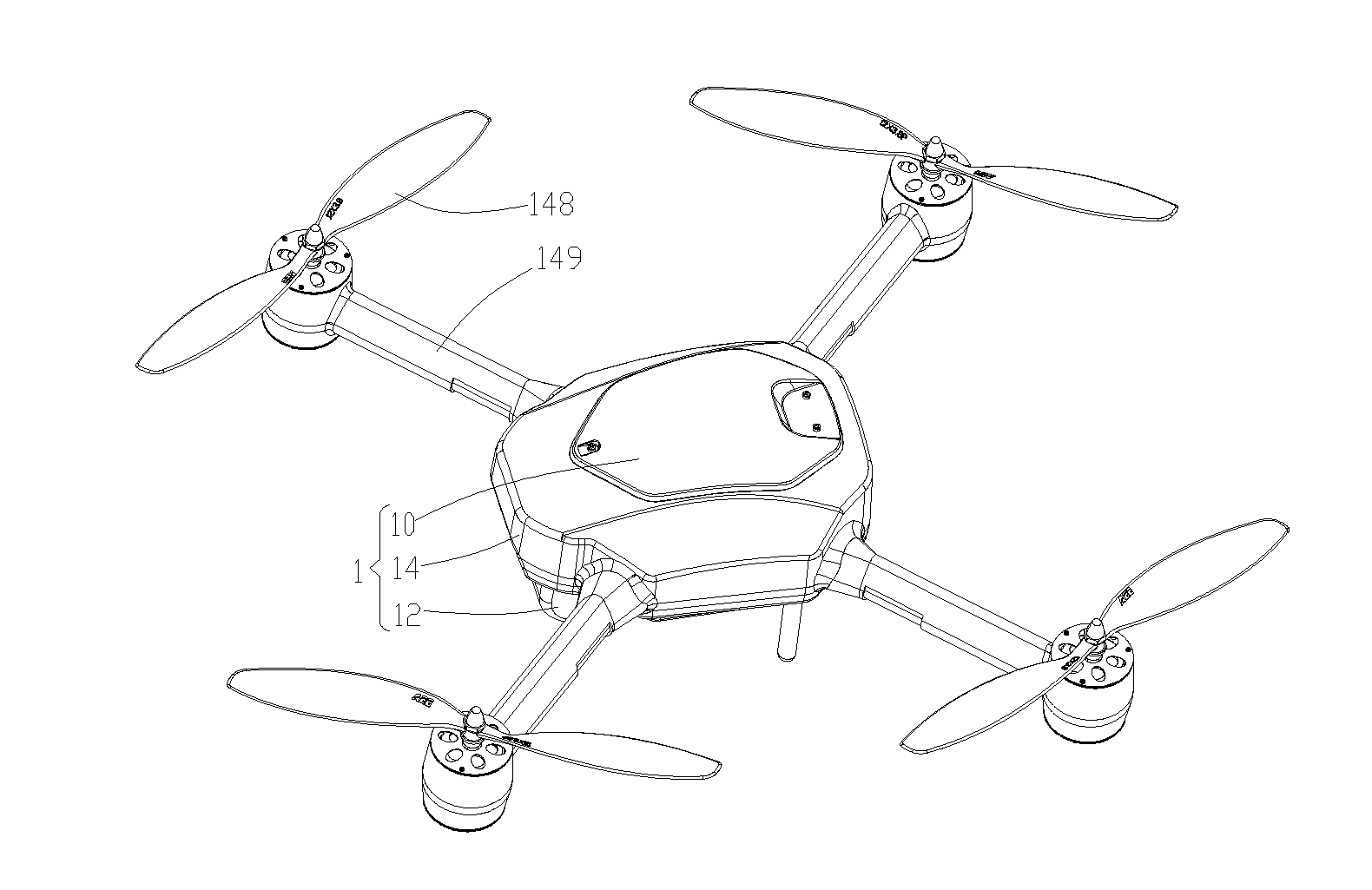
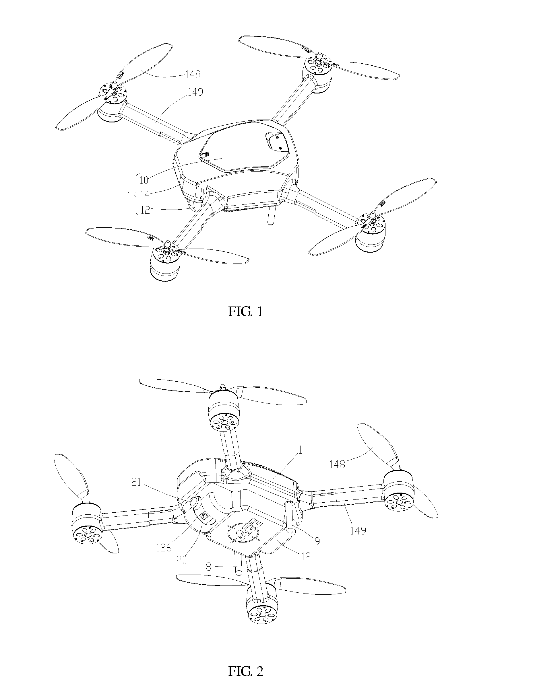
[0039]As shown in FIGS. 1 to 13, an unmanned aerial vehicle in accordance with an embodiment is provided. The unmanned aerial vehicle includes a housing 1 and a remote sensing equipment including but not limited to a camera device, an infrared scanner, and / or radar. The housing 1 includes an upper cover 10, a lower cover 12, and a fuselage 14.

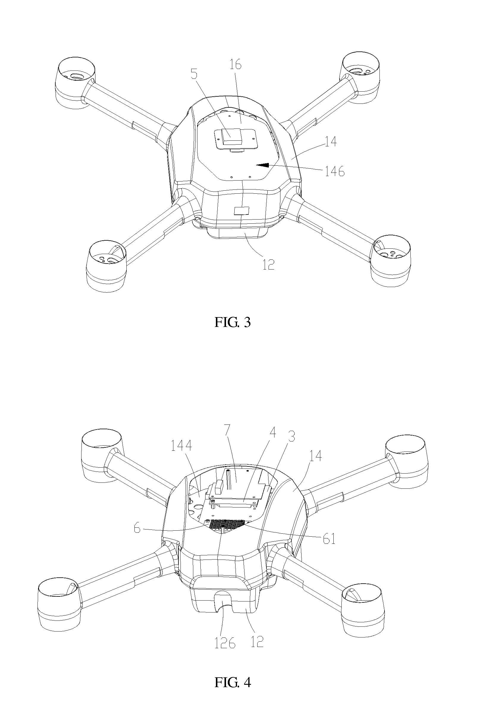
[0040]Referring to FIGS. 5, 6, and 10, the fuselage 14 includes an upper plate 141, a lower plate 142 opposite to the upper plate 141, a connecting plate 143, and a middle spacing plate 144. The connecting plate 143 is connected between the upper plate 141 and the lower plate 142. The upper plate 141, the lower plate 142, and the connecting plate 143 are enclosed to form a receiving space 145 (as shown in FIG. 5). The middle spacing plate 144 is received in the receiving space 145 and di...


PUM

PropertyMeasurementUnit
timeaaaaaaaaaa
thicknessaaaaaaaaaa
conductiveaaaaaaaaaa

Abstract

The present disclosure provides a fuselage of an unmanned aerial vehicle. The fuselage comprises an upper plate, a lower plate opposite to the upper plate, a connecting plate, and a middle spacing plate; the connecting plate is connected between the upper plate and the lower plate; the upper plate, the lower plate, and the connecting plate are enclosed to define a receiving space; the upper plate, the lower plate, the connecting plate, and the middle spacing plate are integrally formed; the upper cavity is located between the middle spacing plate and the upper plate, and the lower cavity is located between the middle spacing plate and the lower plate; and a first mounting opening is defined in the upper plate allowing a component to enter the upper cavity, and a second mounting opening is defined in the lower plate allowing a component to enter the lower cavity.

Description

BACKGROUND[0001]1. Technical Field[0002]The present invention relates to aircrafts, and particularly, to an unmanned aerial vehicle, a fuselage thereof, and a method for manufacturing the fuselage.[0003]2. Description of Related Art[0004]At present, an unmanned aerial vehicle is capable of performing various kinds of reconnaissance and supervision tasks by mounting a visible light camera, a motion picture camera, a standard or low-light level television camera, an infrared scanner, and radar on a housing thereof, therefore, the unmanned aerial vehicle is applicable in fields including security, reconnaissance, and forest fire prevention. However, the unmanned aerial vehicle has following drawbacks: the housing generally includes a front housing and a rear housing which are secured together by a large number of screws, which greatly increases the weight of the unmanned aerial vehicle and affects the flying performance of the unmanned aerial vehicle;[0005]moreover, it is inconvenient ...

Claims


Application Information

Patent Timeline
Patent Type & Authority Applications(United States)
IPC IPC(8): B64C39/02B29C43/00B29C43/18B64C1/00
CPCB64C39/024B64C1/00B29K2021/003B29C43/18B29C43/003B64U10/10B64U30/20
Inventor ZHANG, XIANZHI
Owner SHENZHEN AEE TECH
Why Eureka
Try Eureka