Levitation air plate

Inactive Publication Date: 2015-11-26
OILES CORP
View PDF11 Cites 12 Cited by
  • Summary
  • Abstract
  • Description
  • Claims
  • Application Information

AI Technical Summary

Benefits of technology

[0015]In addition, the present invention relates to a levitation air plate, and the plate is characterized by comprising: a top plate in which a plurality of air ejection holes and suction holes penetrating from an upper surface to an lower surface thereof are arranged in alternating fashion as viewed from the upper surface; a seating face sheet having communicating holes communicated one-to-one with the air ejection holes and the suction holes of the top plate, and penetrating from an upper surface to a lower surface thereof, and whose diameters are larger than diameters of the air ejection holes and suction holes; an orifice sheet having a plurality of first orifices penetrating from an upper surface to a lower surface thereof in positions corresponding to the communicating holes of the seating face sheet communicated with the air ejection holes of the top plate, and having a plurality of second orifices penetrating from the upper surface to the lower surface thereof in positions corresponding to the communicating holes of the seating face sheet communicated with the suction holes of the top plate, a bottom side plate having an air supply route and an air supply hole for supplying air to all of the first orifices drilled in the orifice sheet, and having an air suction route and a suction hole for suctioning air from all of the second orifices drilled in the orifice sheet. With this invention, like the above invention, a glass or the like positioned above can be floated in noncontact state while maintaining its high rigidity, and controlling floatation amount of the substance being conveyed in high accuracy.
[0016]Further, the communicating holes of the seating face sheet form the counter-bored portions, which are provided with the seating face sheet other than the top plate, which can increase accuracy of counter-boring; obtain uniform depth of the counter-bores; and perform the counter-boring with ease.
[0017]In the above levitation air plate, the bottom side plate can be composed of an air route plate and a bottom plate, and on an upper surface of the air route plate is provided air ejecting channel portions that communicate with all of the first orifices drilled in the orifice sheet and suction openings that communicate with all of the second orifices drilled in the orifice sheet; on a lower surf

Problems solved by technology

Then, contact-type conveyors using conventional abacus-type rollers for conveying FPDs have disadvantages in conveying an enlarged glass with thin-wall while increasing velocity; minimizing stress; and conveying with floating amount maintained in high accuracy etc., so that noncontact and air-float conveying is desired.
But, it is difficult to

Method used


Image

  • Levitation air plate
  • Levitation air plate
  • Levitation air plate

Examples


Example

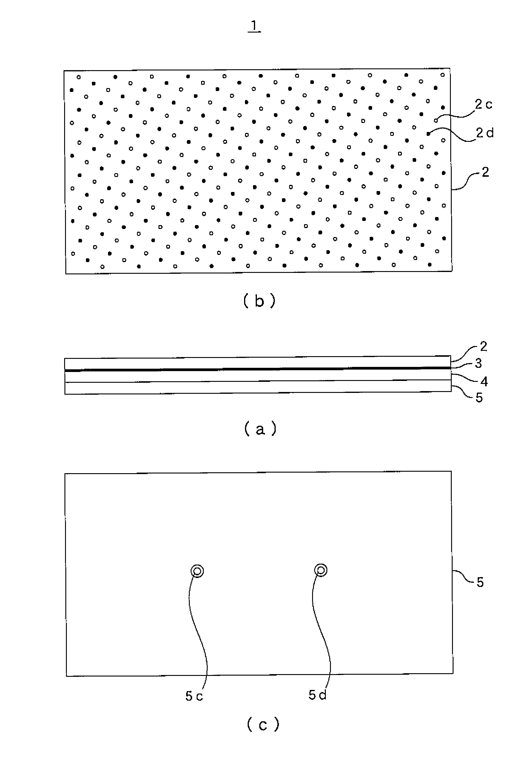
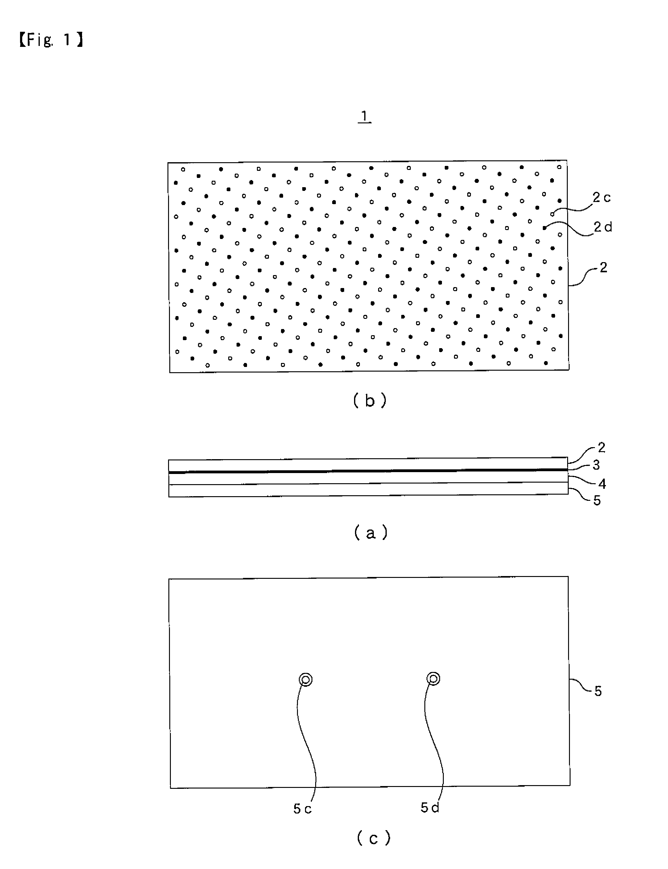
[0037]FIG. 1 shows a levitation air plate according to the first embodiment of the present invention, and this levitation air plate 1 is composed of a top plate 2, in which a plurality of air ejection holes 2c (described with white circles) and suction holes 2d (described with black circles) are arranged in alternating fashion on the upper surface thereof; an orifice sheet 3 positioned under the top plate 2; an air route plate 4 positioned under the orifice sheet 3, and a bottom plate 5 that is positioned under the air route plate 4 and is provided with an air supply hole 5c and a suction hole 5d.

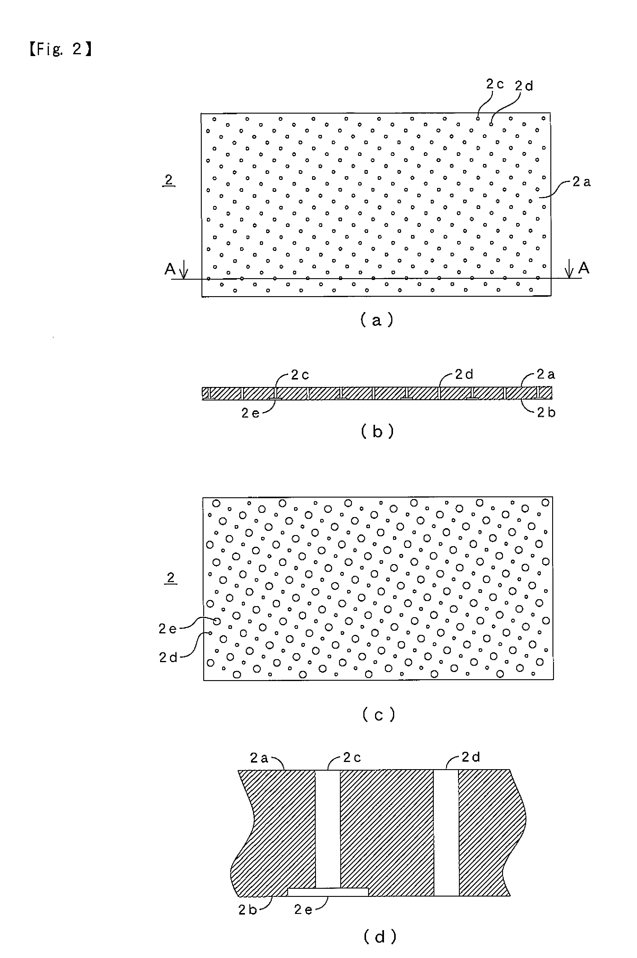
[0038]Surfaces of the top plate 2 are ground with high accuracy, and the top plate 2 is, as shown in FIG. 2, provided with the plurality of air ejection holes 2c and suction holes 2d penetrating from an upper surface 2a to a lower surface 2b arranged in alternating fashion. On the lower surface 2b side of each air ejection hole 2c is formed a counterbored portion 2e. The air ejection hole ...

Example

[0058]Next, a levitation air plate according to the second embodiment of the present invention will be explained while referring drawings.

[0059]FIG. 9 shows a levitation air plate according to the second embodiment of the present invention, and this levitation air plate 21 is composed of a top plate 22, in which a plurality of air ejection holes 22c (described with white circles) and suction holes 22d (described with black circles) are arranged in alternating fashion on the upper surface thereof; a seat face sheet 26 positioned under the top plate 22; an orifice sheet 23 positioned under the seat face sheet 26; an air route plate 24 positioned under the orifice sheet 23, and a bottom plate 25 that is positioned under the air route plate 24 and is provided with an air supply hole 25c and suction holes 25d.

[0060]As shown in FIG. 10, the top plate 22 is, like the top plate 2 in the first embodiment, provided with the plurality of air ejection holes 22c and suction holes 22d penetratin...


PUM


Abstract

To provide a levitation air plate that can be easily manufactured and can float a substance being conveyed such as a glass while maintaining its high rigidity and controlling a floating amount in high accuracy. A levitation air plate 1 provided with: a top plate 2 in which a plurality of air ejection holes 2c and suction holes 2d penetrating from an upper surface 2a to a lower surface 2b are arranged in alternating fashion as viewed from the upper surface, the top plate 2 having a counter-bored portion 2e on the lower surface side of each of the plurality of air ejection holes; an orifice sheet 3 having a plurality of orifices 3c penetrating from an upper surface 3a to a lower surface 3b in positions corresponding to the counter-bored portions of the top plate, and having communicating holes 3d communicated one-to-one with the suction holes of the top plate and penetrating from the upper surface to the lower surface; and bottom side plates 4, 5 having an air supply channel 4c and an air supply hole 5c for supplying air to all of the orifices drilled in the orifice sheet, and an air suction channel 4d and a suction hole 5d for suctioning air from all of the communicating holes communicated with the suction holes.

Description

CROSS-REFERENCE TO RELATED APPLICATIONS[0001]The present application claims priority to International Application No. PCT / JP2013 / 057967 filed on Mar. 21, 2013, which claims priority to Japanese Patent Application No. 2012-084409 filed Apr. 3, 2012 and Japanese Patent Application No. 2013-055853 filed Mar. 19, 2013.STATEMENT RE: FEDERALLY SPONSORED RESEARCH / DEVELOPMENT[0002]Not ApplicableBACKGROUND OF THE INVENTION[0003]1. Technical Field of the Invention[0004]The present invention relates to a levitation air plate, and more particularly to a levitation air plate used for noncontact conveying devices that produce flat panel displays (FPDs) such as large-scale liquid crystal displays (LCDs) and plasma displays (PDPs), solar cell panels (solar panels) and so on.[0005]2. Description of the Related Art[0006]When producing FPDs, solar panels and the like, a method of enlarging one panel to increase production efficiency is employed. Then, contact-type conveyors using conventional abacus-t...

Claims


Application Information

Patent Timeline
IPC IPC(8): B65G49/06B65G51/03
CPCB65G51/03B65G49/065B65G2249/04B65G2249/045H01L21/67784
Inventor TSUNODA, KOUICHIITO, AKIHIKOYASUDA, TAKAHIROOZAWA, HIDEO
Owner OILES CORP
Why Eureka
Try Eureka