Electric blower

a blower and electric technology, applied in the direction of liquid fuel engines, mechanical equipment, machines/engines, etc., can solve the problems of difficult to manage the clearance between the tip of the impeller and the cover at a predetermined level, affecting the performance, and difficult to manage the tolerance between, so as to facilitate the assembly of the impeller and avoid the effect of the separation phenomenon of the impeller and the effect of easy application

Inactive Publication Date: 2015-11-26
SAMSUNG ELECTRO MECHANICS CO LTD
View PDF3 Cites 10 Cited by
  • Summary
  • Abstract
  • Description
  • Claims
  • Application Information

AI Technical Summary

Benefits of technology

[0017]Therefore, in the electric blower according to at least one embodiment of the invention, a hexagonal nut is embedded in the impeller and the impeller is screw-fastened with the shaft of which the end is inserted into the impeller in a shaft direction by the hexagonal nut. Thus, the hexagonal nut blocks a sliding between the shaft and the impeller at the time of the rotation of the impeller to prevent the separation phenomenon from occurring. Further, the assembling of the impeller and the nut more easily assembles the impeller and the shaft than the bonding process.
[0018]According to at least one embodiment of the invention, the nut is fastened with the end of the shaft in a directio

Problems solved by technology

However, the electric blower according to the conventional art, as described, for example, in U.S. Patent Publication No. 2008/0014080 has a structure in which the diffuser and the front are completely fixed to each other by screws, and therefore it is difficult to manage a tip clearance between an impeller and a cover at a predetermined level.
In this case, the tip clearance between the impeller and the cover acts as a factor, which greatly affects the performance.
Further, since the impeller is generally mass-produced using a mold, it is very difficult to manage a tolerance between the components and thus

Method used


Image

  • Electric blower
  • Electric blower
  • Electric blower

Examples


first embodiment

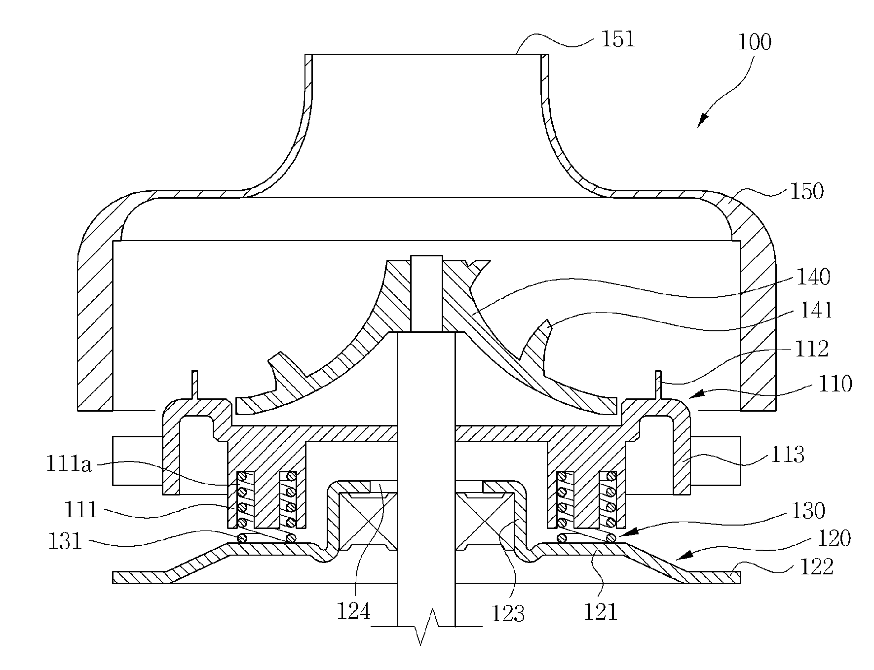
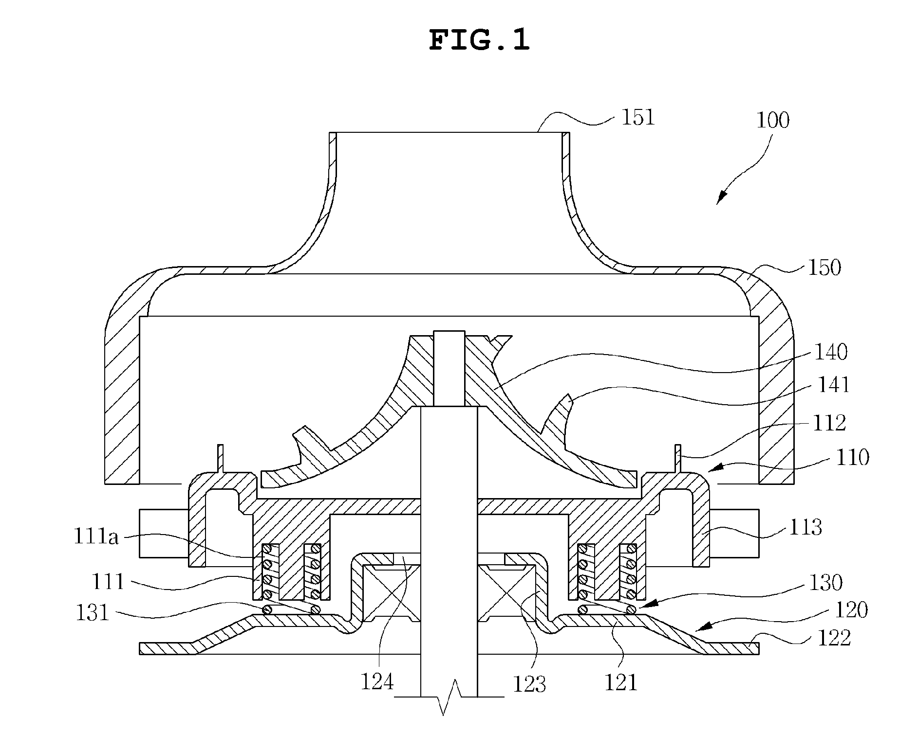
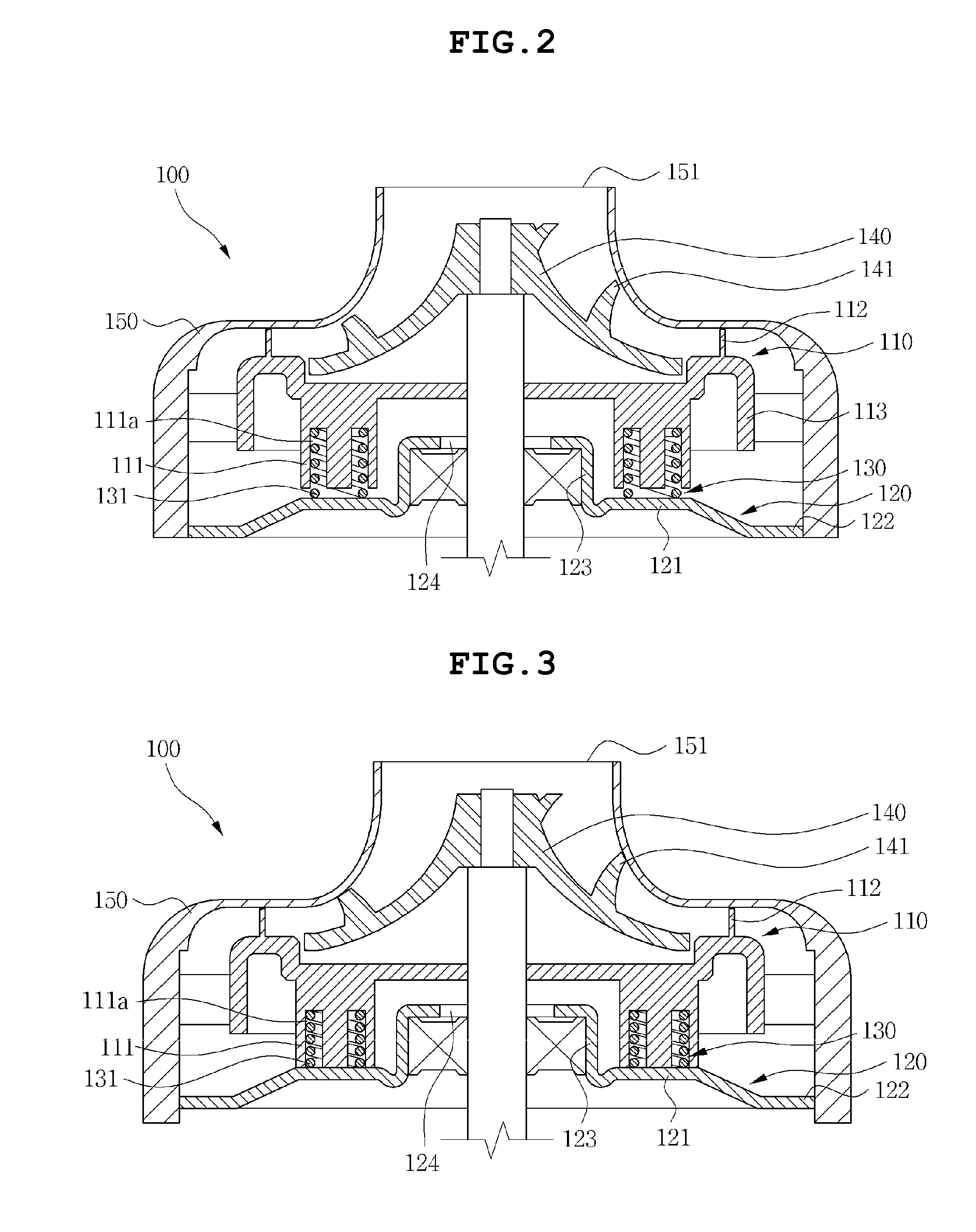
[0029]As illustrated in FIGS. 1 to 3, an electric blower 100, according to a first embodiment of the invention, includes a diffuser 110, a front 120, and an elastic body 130. According to at least one embodiment, the elastic body 130 includes a spring 131. The electric blower has a structure in which the diffuser 110 is disposed at a lower portion in a shaft direction of the impeller 140 in the drawings to guide introduced air and the front 120 is disposed at a lower portion of the diffuser 110 in a shaft direction to support the diffuser 110, and the elastic body 130 is mounted between the front 120 and the diffuser 110.

[0030]According to at least one embodiment, the impeller 140 is provided so that upper ends of wings 141 for introduction of air, for example, are exposed to the outside and thus an inlet 151 into which external air is introduced is received in the cover 150, which is formed at a central portion of the electric blower 100. According to at least one embodiment, the e...

second embodiment

[0040]As illustrated in FIGS. 4 and 5, an electric blower 200, according to a second embodiment of the invention, includes an impeller 240, a shaft 263 with which the impeller 240 is assembled in a shaft direction, and a nut 201 which fastens the shaft 263 with the impeller 240 to assemble the shaft 263 and the impeller 240. In addition, the electric blower 200 further includes a diffuser 210 in which the impeller 240 is disposed at one side in the shaft direction thereof, a cover seating part 212 contacting an inner side of the cover 250 is provided, and a guide part 213 guiding air introduced through an inlet 251 of the cover 250 is formed at an edge of a circumference thereof, a front 220, and a spring 231 mounted in a receiving space 211 a formed at the support part 211 of the diffuser 210.

[0041]According to at least one embodiment, a configuration of the diffuser 210, the front 220, the spring 231, and the cover 250 and a coupling relationship and an acting effect of the compon...


PUM


Abstract

Embodiments of the invention provide an electric blower, including a diffuser having a cover and an impeller sequentially disposed at one side in a shaft direction thereof, a front disposed at the other side in the shaft direction of the diffuser, and an elastic body mounted between the front and the diffuser to support the diffuser.

Description

CROSS REFERENCE TO RELATED APPLICATION[0001]This application claims the benefit of and priority under 35 U.S.C. §119 to Korean Patent Application No. KR 10-2014-0061649, entitled “ELECTRIC BLOWER,” filed on May 22, 2014, which is hereby incorporated by reference in its entirety into this application.BACKGROUND[0002]1. Field of the Invention[0003]The present invention relates to an electric blower.[0004]2. Description of the Related Art[0005]Generally, an electric blower, which is a main body includes a cover and a housing. Further, the electric blower includes, for example, an impeller, a diffuser, and a front, which are installed in an inner space formed by an assembly of the cover and the housing and is disclosed, for example, in U.S. Patent Publication No. 2008 / 0014080.[0006]However, the electric blower according to the conventional art, as described, for example, in U.S. Patent Publication No. 2008 / 0014080 has a structure in which the diffuser and the front are completely fixed ...

Claims


Application Information

Patent Timeline
IPC IPC(8): F04D29/44F04D17/08F04D29/28
CPCF04D29/441F04D17/08F04D29/281F04D17/165F04D29/263F04D29/4253F04D29/622F04D29/626F05D2260/38
Inventor HWANG, SE YEUNJUN, SANG OOKPARK, KYUNG HYUNJUNG, IN YEOPKANG, SEUNG ONPARK, CHANG HWAN
Owner SAMSUNG ELECTRO MECHANICS CO LTD
Why Eureka
Try Eureka