Substrate processing apparatus, cover opening and closing mechanism,shielding mechanism, and method for purging container

a technology for processing apparatus and containers, which is applied in the direction of electrical apparatus, thin material processing, article separation, etc., can solve the problems of difficult to maintain the concentration of inert gas or the like in the main body, and the supplied inert gas or the like is difficult to remain inside the main body, so as to facilitate the maintenance of concentration and avoid the effect of reducing throughpu

Active Publication Date: 2015-11-26
TOKYO ELECTRON LTD
View PDF1 Cites 13 Cited by
  • Summary
  • Abstract
  • Description
  • Claims
  • Application Information

AI Technical Summary

Benefits of technology

[0020]With the present invention, the two plate-shaped movable covers of the shielding mechanism are respectively movable along the opening surface of the opening of the container which is attached to the substrate transfer chamber and whose cover is removed. Therefore, when the two slide cover plates move toward each other, the opening of the container can be shielded. Meanwhile, when a substrate is unloaded from the container, the two slide cover plates are moved away from each other to form a substrate unloading gap at a position corresponding to a position of a substrate to be unloaded. Accordingly, the substrate can be unloaded through the substrate unloading gap without fully openin

Problems solved by technology

The acid gas causes an adverse effect, such as abnormal oxidization of a wiring of the wafer subjected to the plasma processing or the like, on the wafer.
In that case, the generated reaction by-product is adhered to an unprocessed wafer and contaminates it.
Since, however, the opening of the main body of the FOUP is in an open state during the supply of the inert

Method used


Image

  • Substrate processing apparatus, cover opening and closing mechanism,shielding mechanism, and method for purging container
  • Substrate processing apparatus, cover opening and closing mechanism,shielding mechanism, and method for purging container
  • Substrate processing apparatus, cover opening and closing mechanism,shielding mechanism, and method for purging container

Examples


Embodiment Construction

[0029]Hereinafter, embodiments will be described with reference to the accompanying drawings.

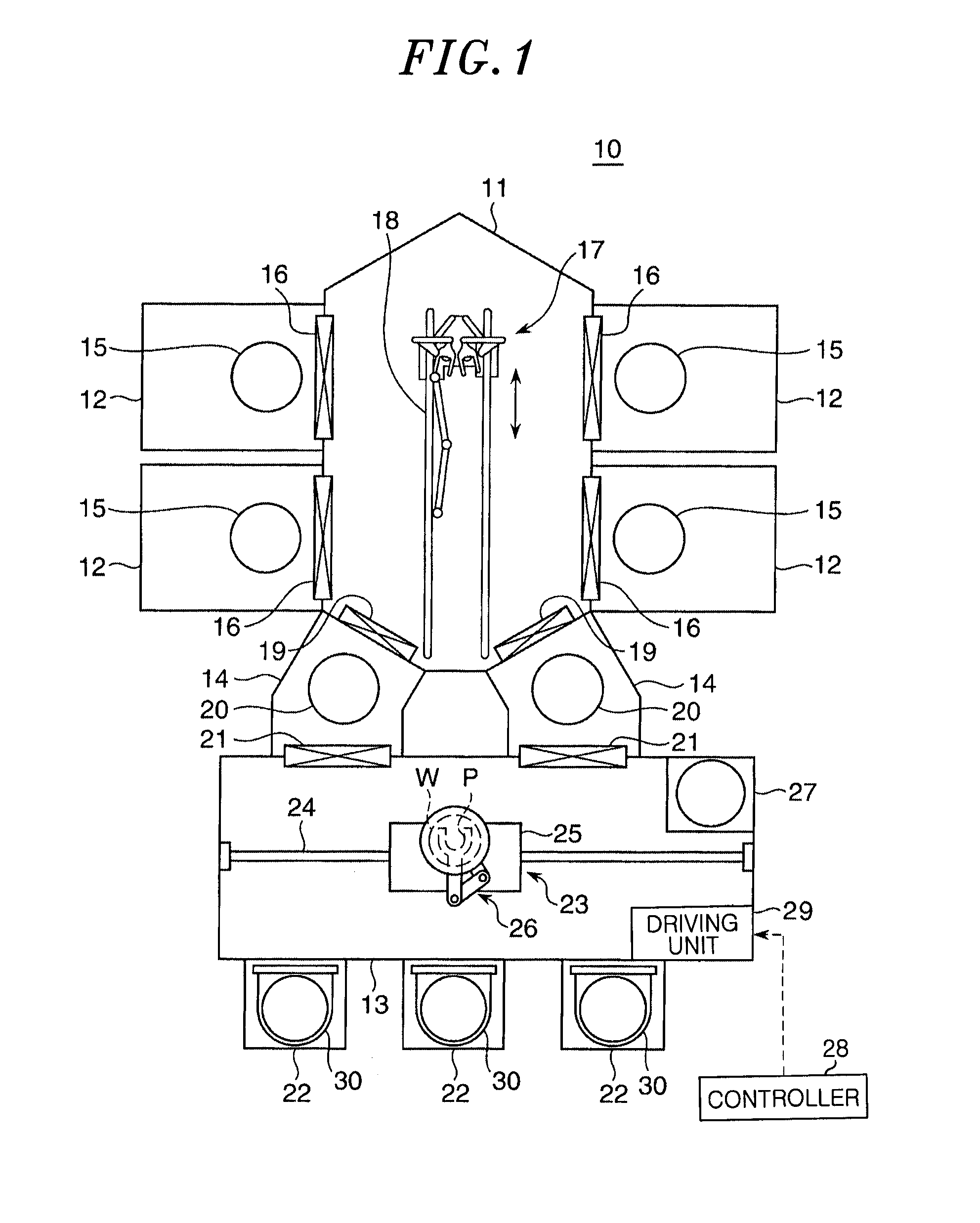
[0030]FIG. 1 is a top view schematically showing a configuration of a substrate processing apparatus according to an embodiment of the present invention. In FIG. 1, the interior of the substrate processing apparatus is shown for ease of explanation. The substrate processing apparatus shown in FIG. 1 is configured to perform plasma processing on one wafer at a time.

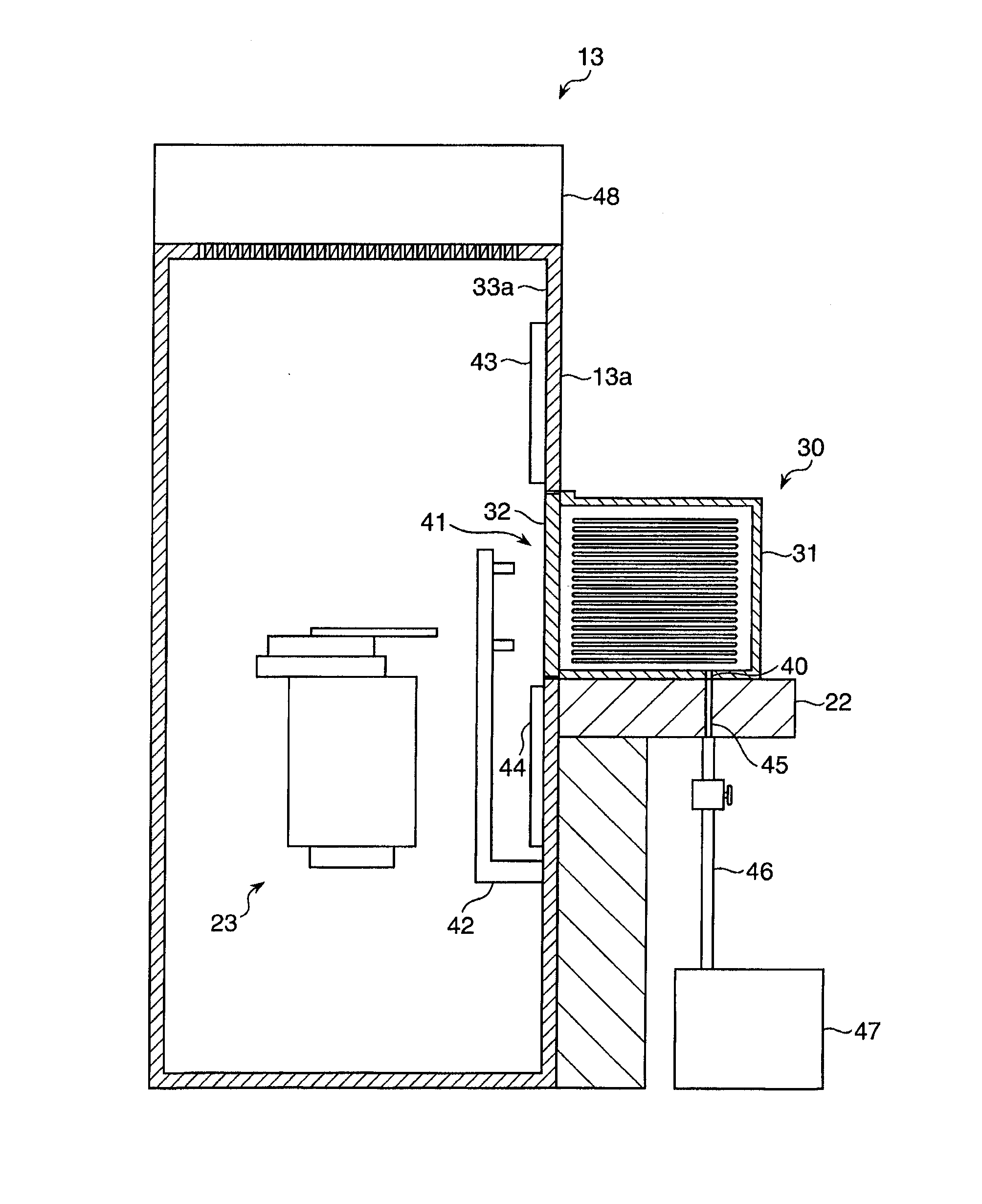
[0031]Referring to FIG. 1, a substrate processing apparatus 10 includes: a transfer module 11 having a substantially hexagonal shape when seen from the top; four process modules 12 disposed at both side surfaces of the transfer module 11; a loader module 13 (substrate transfer chamber) disposed opposite to the transfer module 11; and two load-lock modules 14 provided between the transfer module 11 and the loader module 13.

[0032]Each of the process modules 12 is configured as a vacuum processing chamber in which a stage 15 is provid...


PUM


Abstract

Provided is a substrate processing apparatus that can suppress the amount of inert gas and dry gas used and also can prevent reductions in throughput. A substrate processing apparatus is provided with: a loader module; an opener that removes a cover from a FOUP having a main body, an opening and the cover, to communicate the inside of the FOUP with the inside of the loader module through the opening; an N2 gas supply unit that is attached to the loader module and supplies N2 gas to the inside of the FOUP; and two slide cover plates movable respectively along an opening surface of the opening. The slide cover plates move toward each other until the gap therebetween is 1 mm to 3 mm to shield the opening of the FOUP that is attached to the loader module from the inside of the loader module.

Description

CROSS REFERENCE[0001]This patent application is a national stage of PCT Application No. PCT / JP2013 / 080969, filed on Nov. 12, 2013, which claims priority to and benefit of Japanese Patent Application No. 2012-256778, filed on Nov. 22, 2012. The foregoing patent applications are incorporated by reference for all purposes by their entirety.FIELD OF THE INVENTION[0002]The present invention relates to a substrate processing apparatus using a container that accommodates a plurality of substrates and has an opening and a cover for covering the opening, a cover opening and closing mechanism, a shielding mechanism and a method for purging the container.BACKGROUND OF THE INVENTION[0003]A semiconductor wafer (hereinafter, simply referred to as “wafer”) as a substrate is transferred while being accommodated in an airtight container in order to prevent dirt or the like in the air from being adhered thereto. As for such a container, there is used a FOUP (Front Opening Unified Pod) specified by SE...

Claims


Application Information

Patent Timeline
IPC IPC(8): H01L21/673H01L21/677
CPCH01L21/67376H01L21/67393H01L21/67373H01L21/6773H01L21/67772
Inventor WAKABAYASHI, SHINJI
Owner TOKYO ELECTRON LTD
Why Eureka
Try Eureka