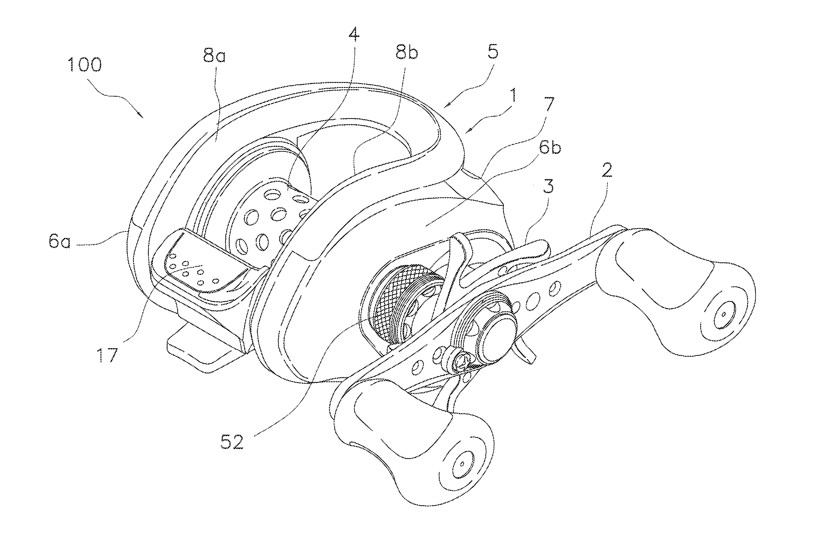
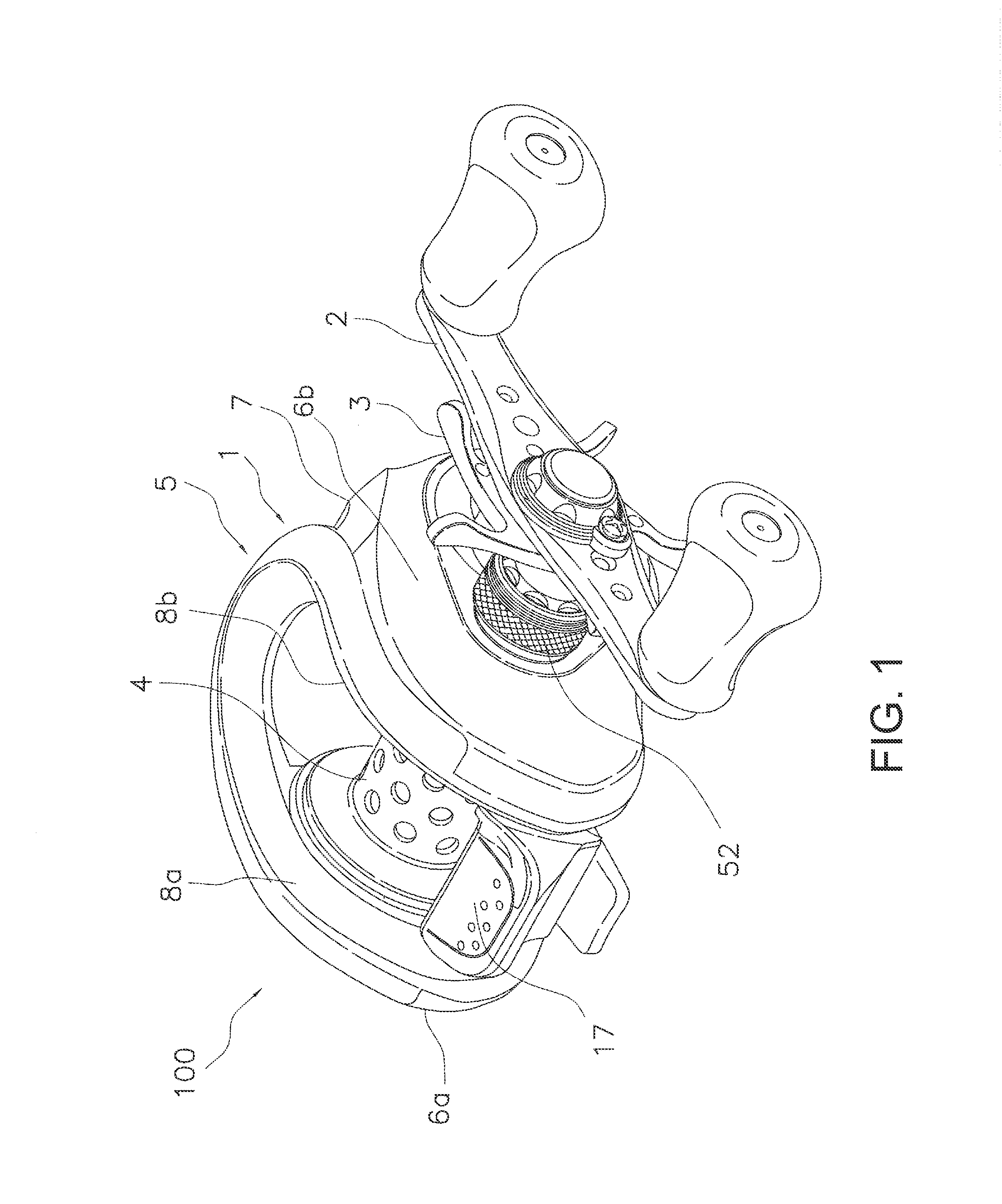
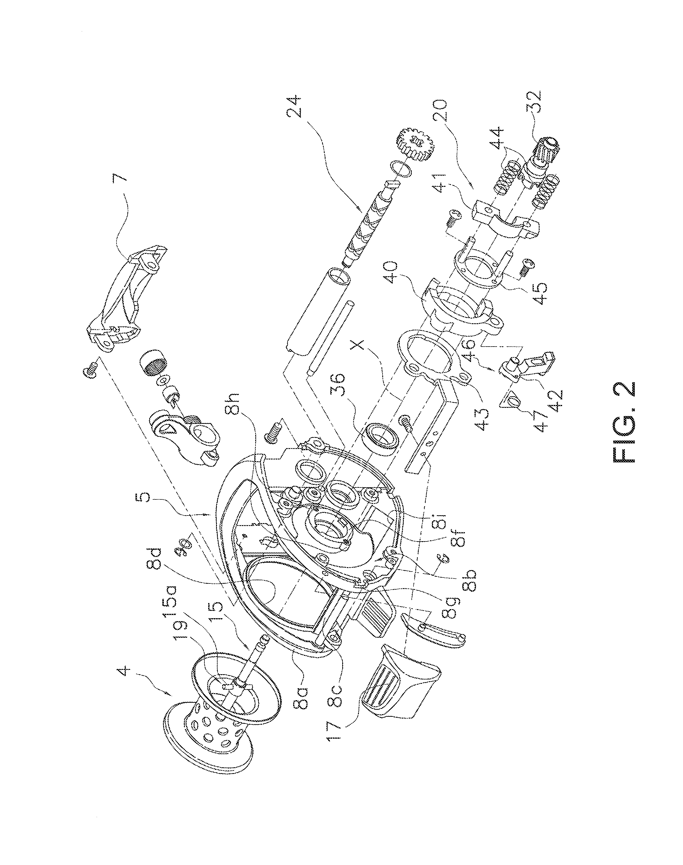
Clutch return mechanism for a dual-bearing reel

a dual-bearing, clutch-type technology, applied in the direction of reels, applications, fishing, etc., can solve the problems of reducing the weight of the risk of the clutch cam being deformed, and the inability to obtain the strength that is necessary for the clutch-type return member in this manner, so as to secure the necessary strength and secure the flexibility. , the effect of simple configuration

Active Publication Date: 2015-12-03
SHIMANO INC
View PDF4 Cites 12 Cited by
  • Summary
  • Abstract
  • Description
  • Claims
  • Application Information

AI Technical Summary

Benefits of technology

[0011]The object of the present invention is to reduce the weight while maintaining the strength of the clutch return member, and while preventing deformation of the clutch cam in a clutch return mechanism of a dual-bearing reel.
[0024]According to the present invention, it is possible to secure the necessary strength with the metallic reinforcing member, and secure the flexibility and reduce the weight in order to prevent the deformation of the clutch cam with the synthetic resin body member. As a result, reducing the weight while maintaining the strength of the crank member and while preventing the deformation of the clutch cam is possible.

Problems solved by technology

Conventionally, since the rotational force of a clutch return member made of a hard material that is not easily plastically deformed is directly transmitted to the synthetic resin clutch cam, when excessive rotational force is applied, there is the risk that the clutch cam will be deformed.
Additionally, since the clutch return member is made of metal, reducing the weight of the clutch return member can be difficult.
In order to solve this problem, forming a clutch return member from a relatively soft material, such as resin, is conceivable; however, the strength that is necessary for a clutch return member cannot be obtained in this manner.

Method used


Image

  • Clutch return mechanism for a dual-bearing reel
  • Clutch return mechanism for a dual-bearing reel
  • Clutch return mechanism for a dual-bearing reel

Examples


second embodiment

[0085]In the first embodiment, the reinforcing member 52 of the clutch pawl 42 was insert molded and integrally formed with the body member 50; however, in a clutch return mechanism 146 of the second embodiment, as shown in FIGS. 8 and 9, a reinforcing member 152 of a clutch pawl 142 is separate from a body member 150. In the second embodiment, the members corresponding to those described in the first embodiment are shown with reference symbols having added “100” added to the reference symbols used in the first embodiment.

[0086]The body member 150 comprises a pivot shaft 150a, a coupling protrusion 150b, a first surface 150c, a spring locking portion 150d, and a regulating protrusion 150e configured in the same way as in the first embodiment. The body member 150 further comprises a second surface 150f that is disposed to be parallel to the pivot shaft 150a. The body member 150 comprises a first connecting portion 150g that is integrally coupled to one end of the pivot shaft 150a on ...


PUM


Abstract

A clutch pawl includes a synthetic resin body member and a metallic reinforcing member. The synthetic resin body member is pivotally mounted to a clutch cam. The metallic reinforcing member integrally pivots with the body member and reinforces the body member. The toggle spring member divides and biases the clutch pawl to the engaged position and the separated position.

Description

CROSS-REFERENCE TO RELATED APPLICATIONS[0001]This application claims priority to Patent Application JP 2014-114752 filed on Jun. 3, 2014, the contents of which is hereby incorporated herein by reference.BACKGROUND[0002]1. Field of the Invention[0003]The present invention relates to a clutch return mechanism and, specifically, to a clutch return mechanism for a dual-bearing reel for returning a clutch cam from a released position, in which a handle and a spool of a dual-bearing reel are in a released state, to a coupled position, in which the handle and the spool are coupled.[0004]2. Background Information[0005]A clutch mechanism is generally disposed between a handle and a spool of a dual-bearing reel (for example, refer to Japanese Laid-Open Patent Publication No. 2012-65574). The clutch mechanism is in a clutch-on state for coupling the handle and the spool and a clutch-off state for releasing the handle and the spool. In the clutch-on state, the spool is capable of being rotated ...

Claims


Application Information

Patent Timeline
Patent Type & Authority Applications(United States)
IPC IPC(8): A01K89/015
CPCA01K89/0189A01K89/01901A01K89/015A01K89/0186
Inventor TAKECHI, KUNIO
Owner SHIMANO INC
Why Eureka
Try Eureka