Ceiling suspension system

a suspension system and ceiling technology, applied in the field of acquisition of medical image information of objects, can solve the problems of increasing complexity of x-ray interventions, achieve the effects of reducing the distance between operating staff and required equipment, improving visibility, and improving working conditions

Inactive Publication Date: 2015-12-03
KONINKLJIJKE PHILIPS NV
View PDF6 Cites 6 Cited by
  • Summary
  • Abstract
  • Description
  • Claims
  • Application Information

AI Technical Summary

Benefits of technology

[0060]An advantage of the further equipment items can be to provide staff with further improved working conditions. In particular, a distance can be minimized between operating staff and required equipment. This can lead to improved visibility and improved information accessibility to provide more effective interventions.
[0061]In another example, the movable lighting equipment or movable display equipment or media rack are disposed outside the patient access zone, outside the patient support, or a combination of both. In general, the aim is to minimize a risk of collision of an equipment and / or staff. For example, lighting equipment, display equipment, media racks, and others can be mounted using a suspension at the ceiling, which is achieved with a further or second orthogonal or transversal rail system at an opposing end of the patient support. This provides furthermore a possibility to move such equipment completely out of way, if not needed. The term “media rack” refers to a supply unit for further media and extended functions.

Problems solved by technology

X-ray interventions become more and more complex, in particular due to the required systems and devices, as well as staff and third party equipment.

Method used


Image

  • Ceiling suspension system
  • Ceiling suspension system
  • Ceiling suspension system

Examples


Embodiment Construction

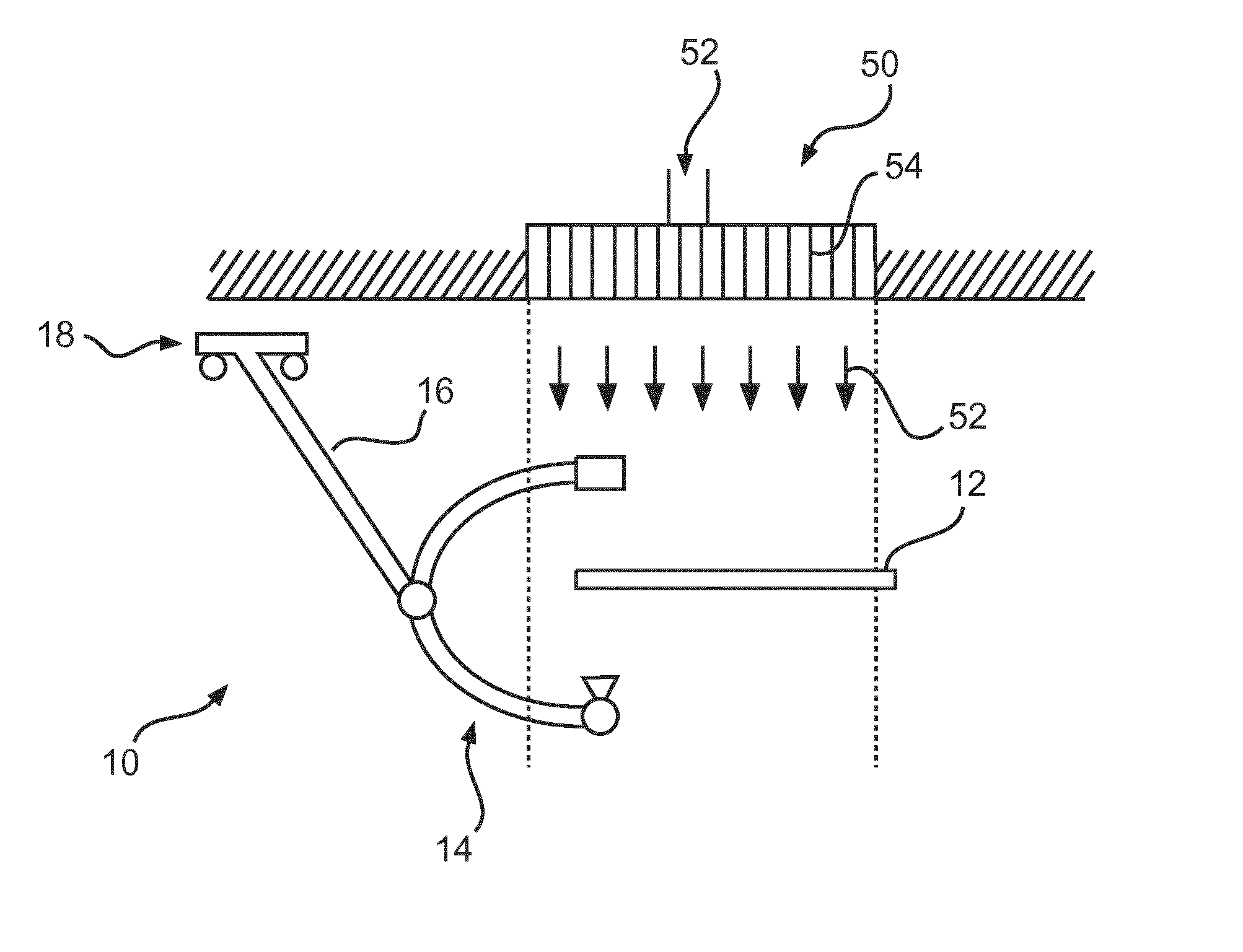
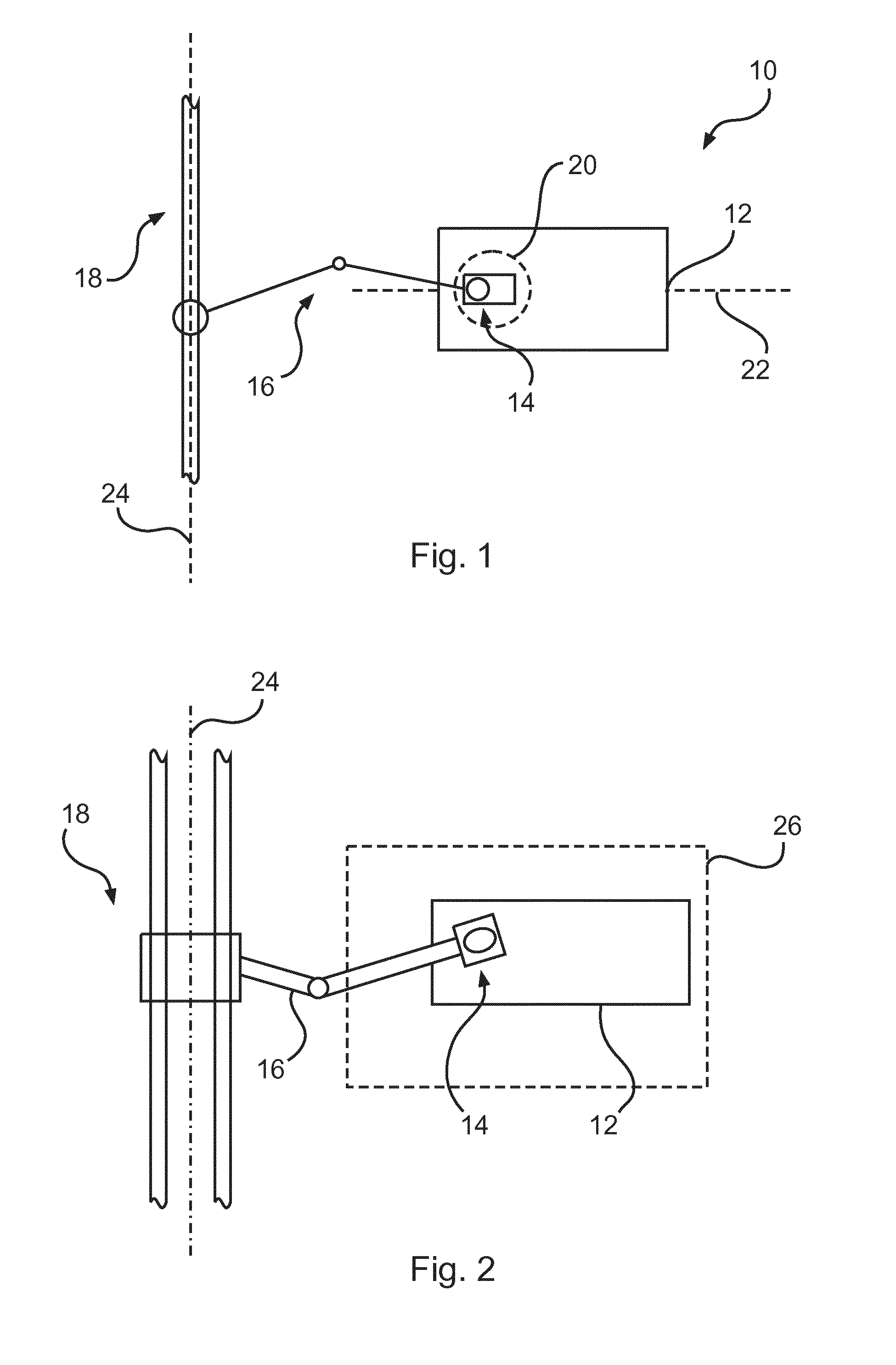
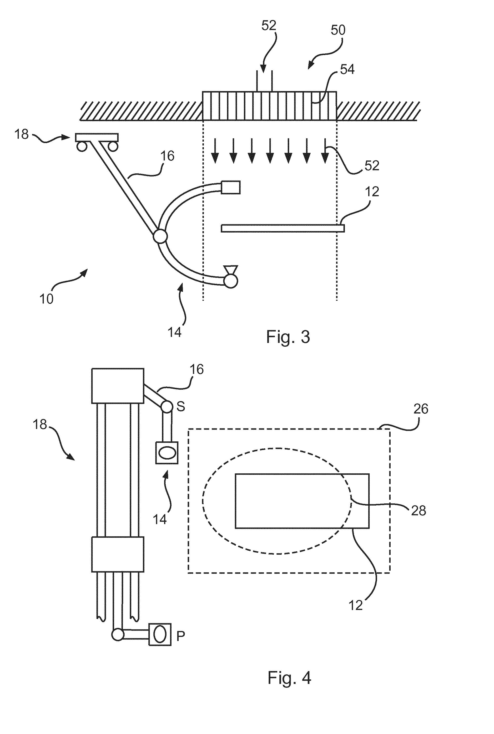
[0071]FIG. 1 describes a medical imaging system 10 based on X-ray for generation of imaging information of an object 20. The medical imaging system 10 comprises a patient support 12, which has a longitudinal horizontal extension or direction 22. A rail arrangement 18 has a longitudinal rail direction 24 and is mounted to a support arrangement 16. The support arrangement 16 is movably connected to the image acquisition arrangement 14. The rail arrangement 18 is transversely, or as shown in FIG. 1, orthogonally arranged in relation to the longitudinal extension 22 of the patient support 12.

[0072]The rail arrangement 18 can comprise one or several distinct rails which can be arranged such that a moving of the support arrangement 16 along the rails is possible. Instead of an exact orthogonal arrangement of the rail arrangement 18, also all other angles except a parallel arrangement related to the longitudinal extension 22 of the patient support 12 are possible. The rail arrangement 18 c...


PUM


Abstract

The present invention relates to acquisition of medical image information of an object. In order to improve operating theatres and allow more effective use of equipment and staff during interventions, a medical X-ray system (10) is provided, comprising a patient support (12), an X-ray image acquisition arrangement (14), a support arrangement (16), and a rail arrangement (18). The image acquisition arrangement (14) acquires imaging information of an object of interest (20) arranged on the patient support (12). The rail arrangement (18) is provided overhead. The support arrangement (16) is movably mounted to the rail arrangement (18), and at least movable along the rail arrangement (18). The image acquisition arrangement (14) is movably mounted to the support arrangement (16) to allow image acquisition of the object (20) from different directions. The rail arrangement (18) is arranged transversely to a longitudinal direction of the patient support.

Description

FIELD OF THE INVENTION[0001]The present invention relates to acquisition of medical image information of an object. In particular, the present invention relates to a medical X-ray imaging system for providing medical imaging information of an object.BACKGROUND OF THE INVENTION[0002]X-ray interventions become more and more complex, in particular due to the required systems and devices, as well as staff and third party equipment. In particular, fixed X-ray systems are often used in operating theatres to enable minimally invasive or mixed procedures. With the evolution of methods and available technologies, such operating theatres comprise an increasing number of equipment and medical staff. An effective cooperation of involved equipment and staff can be become important for effective interventions. WO 2010 / 137116 A1 describes a safety system for a dynamic 3D health care environment and a medical examination system with motorized equipment.SUMMARY OF THE INVENTION[0003]Hence, there may...

Claims


Application Information

Patent Timeline
Patent Type & Authority Applications(United States)
IPC IPC(8): A61B6/00
CPCA61B6/4464A61B6/4423A61B6/4441
Inventor JANSSEN, ERIK JOHANNES MARIAVAN GARDEREN, JOHANNES HERMAN HUBERTUS MATHIJSDRIES, JOHAN JULIANAVAN DER STAPPEN, ARNOLDUS JOHANNES MARIA
Owner KONINKLJIJKE PHILIPS NV
Why Eureka
Try Eureka